
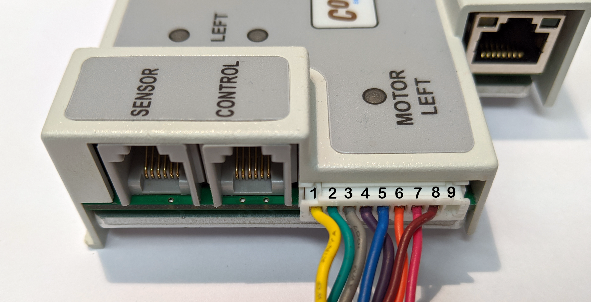
Both the Left and the Right Motor Ports utilize a 9-pin JST brand female receptacle. Each receptacle is mechanically keyed to assure proper orientation upon plugging in. The motor connector pin-outs are as shown
| Pin | Description |
|---|---|
| 1 | GND |
| 2 | Vcc – Hall Effect Sensor Power |
| 3 | Motor Winding U |
| 4 | Motor Winding V |
| 5 | Motor Winding W |
| 6 | Hall Effect Sensor U |
| 7 | Hall Effect Sensor V |
| 8 | Hall Effect Sensor W |
| 9 | Optional – Mechanical Holding Brake Control |