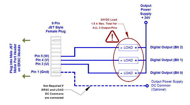
External controller must first set bit 15 = 1 in the Set Left/Right Motor Port Digital Control register for the motor port (Left or Right) that is to be used as digital output. If bit 15 = 0, then the ERSC ignores the bit 0 thru bit 2 commands and will not provide meaningful status on bits 12 and 14 in the corresponding Left/Right Motor Port Digital I/O Status register for the port in question. Bit 0, bit 1, and bit 2 can be independently set and reset by the PLC and all 3 digital outputs can be energized simultaneously.
Using the Brake Output Pin on the Motor Port
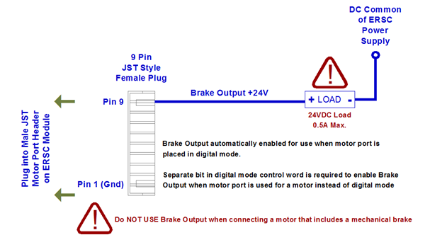
You can also utilize the Brake Output (Pin 9 on the JST connector) as a +24V output signal controlled from your PLC program when the ERSC is in PLC I/O mode. This signal sources +24V and is limited to 0.5A load.
When using the Brake Output when the port is actually running a motor, you must set bit 7 in the appropriate left or right “Set Motor Port Digital Control” output word in order to enable the Brake Output functionality. Once you do this, then bit 6 in the same word controls the on/off state of the digital signal. If you have enabled the motor port for digital control by setting bit 15, you do not have to also set bit 7 to enable the Brake Output. It is already enabled when you set bit 15


