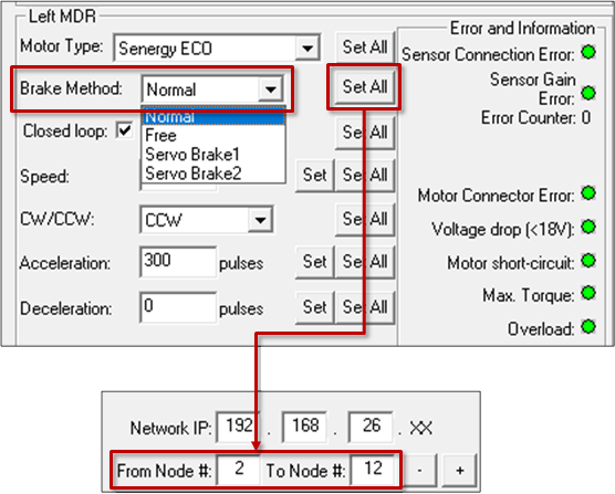
The Brake Method drop-down box lists all the holding brake methods available for the module. Normal is the default setting upon completion of the Auto-Configuration Procedure. The new settings are downloaded to the selected Node upon selecting a new item from the list.
| Selecting a Brake Method from the drop down box immediately makes the change for the current Node. Clicking Set All will download the selected setting to the Left MDR of all modules entered in the range of Nodes at the top of the main screen in the From Node # / To Node # boxes. In our example, the From Node # / To Node # boxes have the values of 2 and 6. Changing the selection in the Brake Method drop down will change Node 2 and then by clicking Set All it will change Nodes 3 thru 12 to the same setting as Node 2 |
![]() |
| Method |
>Description |
| Normal |
Once the controls have decelerated the rotor to a stop, the motor coil are internally connected. The permanent magnet forces in the rotor and the mechanical inertia of the gearbox holds the rotor in place. This is the MDR industry standard holding brake method and is often termed short circuit or shunt. Normal is the default factory setting for all module zones from the Auto-Configuration Procedure |
| Free |
Once the controls have decelerated the rotor to a stop, the motor coils are internally disconnected and only the mechanical gearbox inertia holds the rotor in place |
| Servo Brake 1 |
When the controls have decelerated the rotor to a stop, the processor notes the Hall Effect sensor status. If the Hall Effect sensor status changes indicating a change in position of the rotor, the controls will inject current into 2 of the 3 motor coils in the proper sequence to move the rotor back to its original stop position |
| Servo Brake 2 |
When the controls have decelerated the rotor to a stop, the processor notes the Hall Effect sensor status. If the Hall Effect sensor status changes indicating a change in position of the rotor, the controls will inject current into all 3 of the motor coils in the proper sequence to move the rotor back to its original stop position |
*Please note that if you change the Brake Method and this module goes through another Auto Configuration procedure, the Brake Method setting will not reset back to default. It will remain unchanged at the last selected setting.
!Servo Brake 1 and 2 are functionally equivalent. Servo Brake 2 utilizes more power and provides more holding torque. Consequently, because Servo 2 uses more current, the potential for heat build-up is present depending on your application. If Servo Brake 1 provides enough holding torque for the application, it is recommended using it in lieu of Servo Brake 2. Servo Brake 2 should only be used when Servo Brake 1 does not provide enough holding torque for the application


