
At the rear panel of the device can be found the following information:
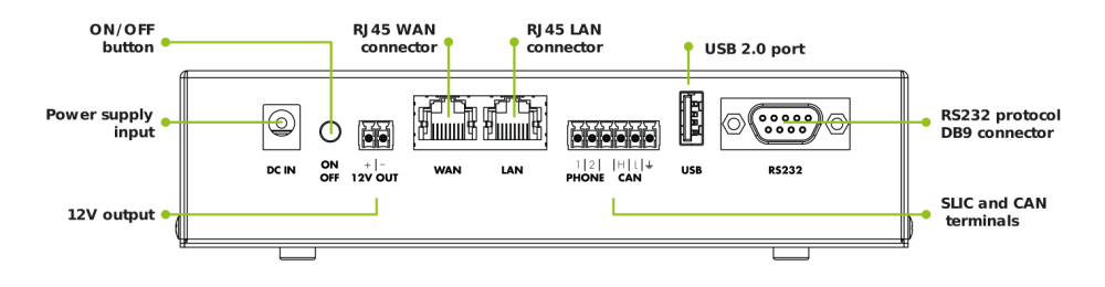
DC IN
Input for the power supply. When possible, the device must be always powered with the original power supply. In case the original power supply can not be used, it is recommended to use a 18V-24V and 2A power unit for an optimal battery charge.
ON / OFF
Button used for turning ON or OFF the device. When OFF, all current passage is interrupted from both power supply and the battery.
12V OUT
12V output with polarity as indicated in the graphic. It can be used to connect several autodialers in case they need external power, taking into consideration that the maximal supported current is 1A.
WAN/LAN
- WAN: RJ45 connector to receive internet connectivity from other devices.
- LAN: RJ45 connector to supply internet connectivity to other devices.
PHONE / CAN
GSR can be connected to autodialers through the integrated SLIC or CAN modules. To do so, the device has terminal connectors that must be used as described:
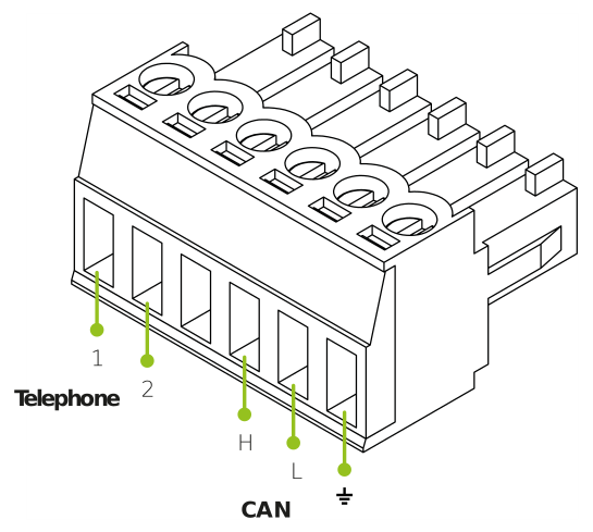
- 1 y 2 (phone line): the pair of phone line wires or TIP and RING have to be connected to the first two positions as indicated. The order of the connectors does not affect the signal.
- H, L and GND (CAN connection): to ensure a correct operation, special attention must be paid when connecting H, L and GND. Please follow the indica ted steps.
USB
Compatible with USB 2.0 (0.5A) devices like for example expansion modules, a bluetooth adaptor, a webcam, etc.
RS232
Male DB9 connector. Compatible with RS232 standard (DCD,RTS/CTS,RI, DSR). It is the access point to the control panel or other devices using this communication standard.