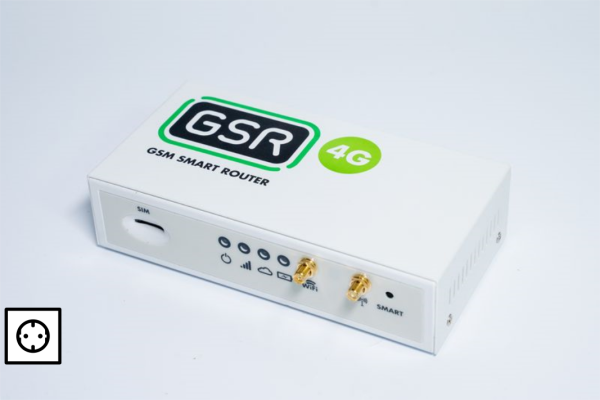
1º Material supplied.
The contents of the GSR box consist of a WIFI antenna, a 3G/4G antenna, a 3-wire charger and a GSR device, as shown in the picture below.
2º GSR ID
The MAC number on the back sticker of the GSR is the unique device identifier that will be indicated throughout the installation and commissioning process.
 |
3º GSR installation on DIN rail
If the installation requires it, the DIN rail brackets are mounted on the GSR, screwed to the rear and the rail is inserted from the side and then screwed into the lift shaft, following the steps below.
4º Insert SIM
Insert the SIM card by sliding it into the slot and pressing it until it clicks as shown in the picture.
5º 3G/4G antenna connection
The antenna corresponding to 3G/4G is connected. This antenna must always be connected to the device in the indicated connector.  |

 |
6º Precautions
The power supply is connected taking into account that it is a power supply point with compatible voltage 220V AC, stable and without automatic or manual disconnection.
7º Power supply
Connect the power supply to the 18V GSR included in the box and press the power button as shown in the following pictures.

Once the power button has been pressed, wait for the device to connect to the mobile network and get coverage, maximum 5 minutes.
8º APN configuration (optional)
9º GSR update
We wait about 20 minutes for the GSR to connect to the NAYAR server, download the updates and configuration necessary for the correct operation of the GSR.
During the download and update process the GSR will reboot several times.
It is important that the GSR is not handled until this process is complete and the GSR is OK. If all LEDs are flashing, do not switch off for 15 minutes. A software update is in progress.

10º GSR OK
After the update the 3 GSR LEDs will stay on.

11º Switch on controler
Check that all the wiring, connectors and components required for connection of the controller are in place according to the installation guide supplied with the installation kit.
Install the necessary connections for the controller. Technician’s View
Start technical view app. Link to manula manual.
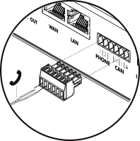
12º Connecting a telephone line
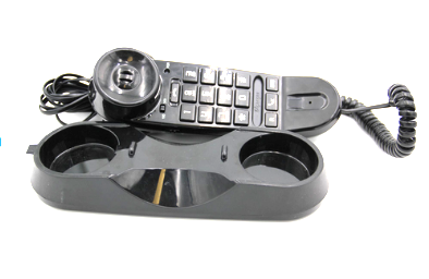
Connect telephone line output to the tele-alarm and install telephone line from the GSR to the TA. An analogue telephone is connected to test that the incoming/outgoing call works.
 |
 |
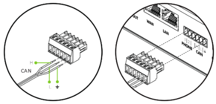
13º Connect to tele-alarm (optional)
Wire the terminal with the CAN communication wires to the alarm device if necessary.
14º GSR Config
1.Required data.
GSR MAC
Telephone number
Control and/or tele-alarm model
ID / reference
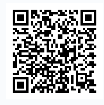
2.Access the configuration application.
| Return to ‘Commissioning APP ‘ |
|---|
 |
15º Useful links
| Return to ‘Troubleshooting Guide’ | Return to ‘Technician View Troubleshooting’ |
|---|---|
 |
 |


