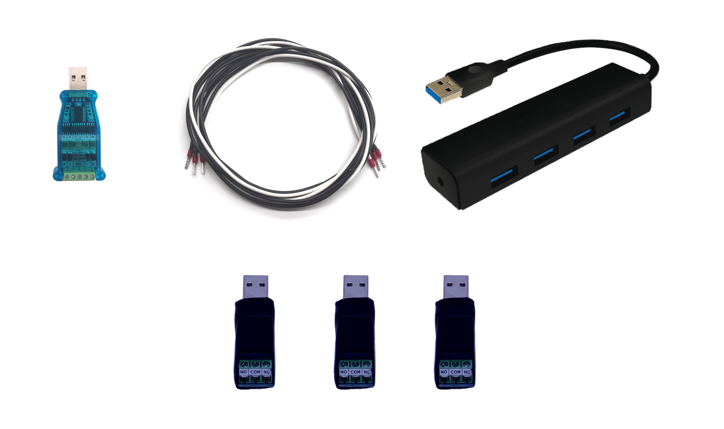
1. Material required
- USB to RS422/485 adapter, USB HUB, 3x USB RELAY v1, pair of CAN wires.
 |
| SJEC Toolkit |
2. Connection to control system
- Locate connector SL2
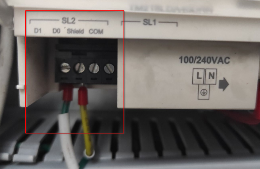
- Make the following connections to the USB to RS422/RS485 adapter
| SL2 connector | USB to RS422/RS485 adapter |
|---|---|
| D0 | A |
| D1 | B |
- Connect terminal 5 of the USB to RS422/RS485 adapter to a PLC ground.
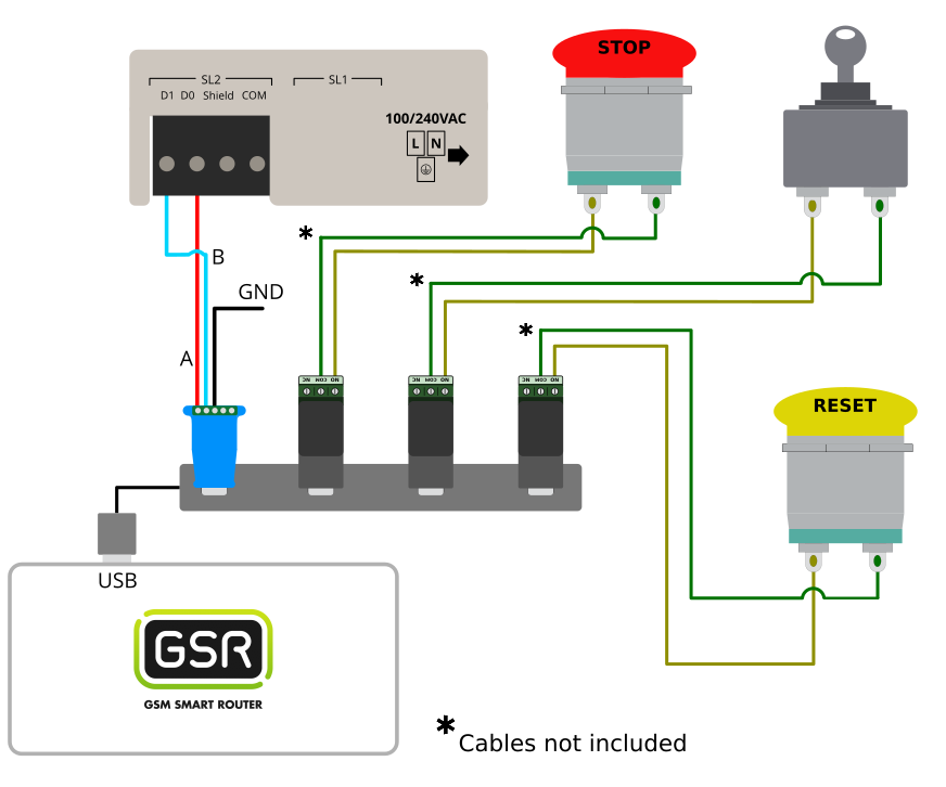
- Connect the NO contact of the first USB relay v1 to one of the terminals of the Stop button.
- Connect the NO contact of the second USB relay v1 to one of the terminals of the Key.
- Connect the NO contact of the third USB relay v1 to one of the terminals of the Reset button.
- Connect the USB to RS422/RS485 adapter and the three USB Relay v1 to the USB Hub.
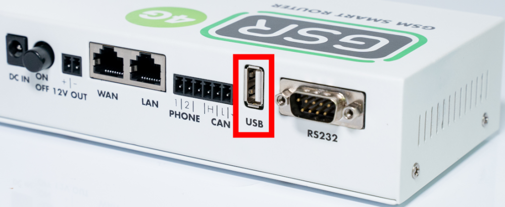
- Locate the USB connector on the GSR and connect the USB HUB to that connector.
![]()
- Connect the USB to RS422/RS485 adapter to the USB port of the GSR.
3. Configuration in SmartControl
Once we have the elements installed, we continue the process in the SmartControl platform.
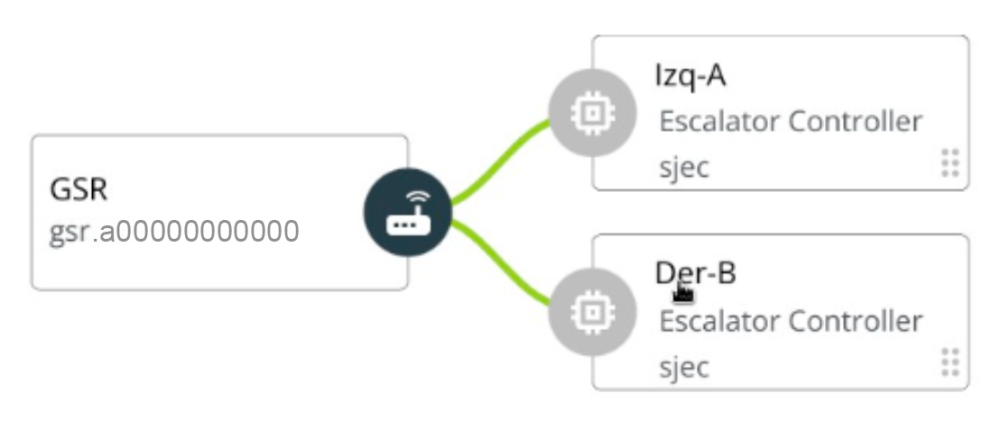
1.First of all you must make sure that the reference (name) of the SJEC element follows one of the following options:
- TAG-NAME (example: ESCALERA IZQ-A)
- TAG (example: A)
In this way, each ladder has its own TAG, so if you want to have more than one ladder per GSR, the following ladders must have a unique TAG.
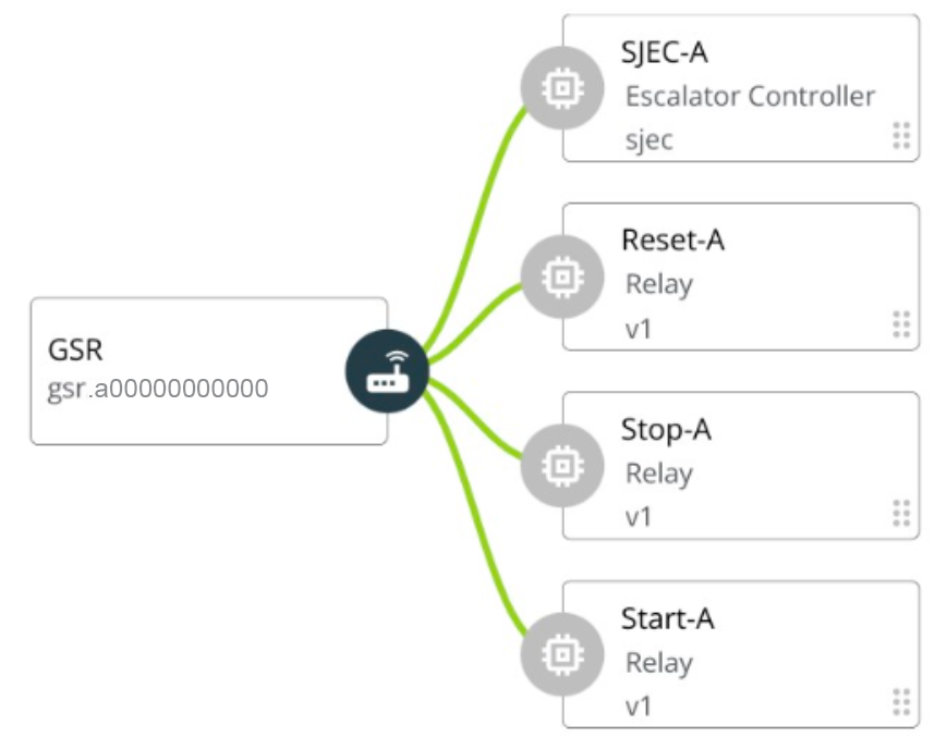
2. The customer must then individually link each relay element and follow the installation process. At the end each of the relays must have a name, which, unlike the ladder, is specific to the functionality of each relay, it must follow the NAME-TAG rule:
- Start-TAG for the start relay.
- Stop-TAG for the stop relay.
- Reset-TAG for the reset relay.
Copyright © 2025 Nayar Systems
—
Powered by