1. Required elements
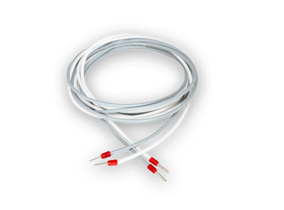
- 2x wires for CAN connection
 |

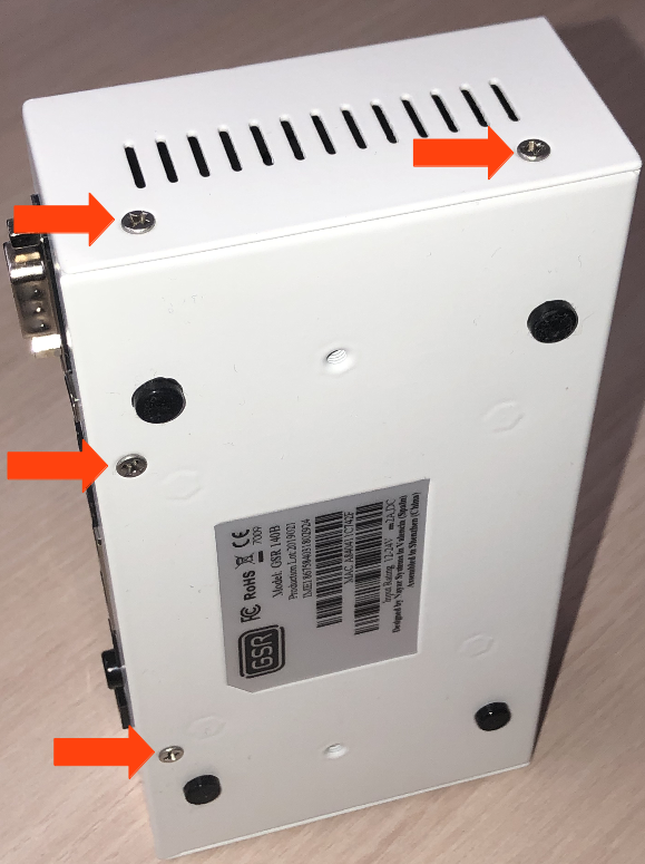
1. Remove the 6 screws from the base and sides
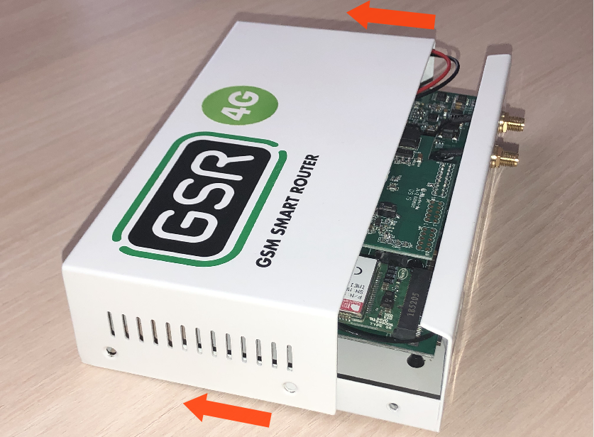
2. Slide the cover until it is removed from the GSR
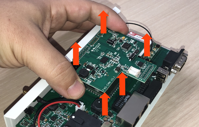
3. Remove the FXS-CAN board pulling gently and equally on both sides
4. Turn around and check that the jumpers are on
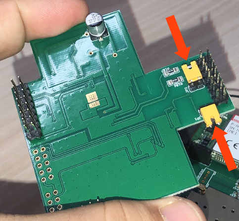
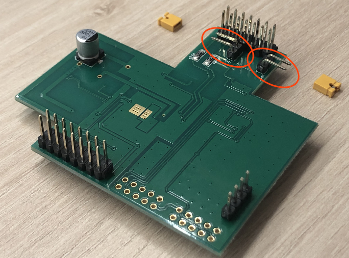
5. Remove the jumpers to deactivate the resistors
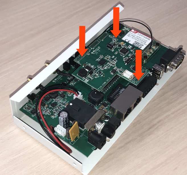
6. Place the FXS-CAN gently, confirming that all pins are aligned correctly
7. Reverse the steps to re-assemble the GSR
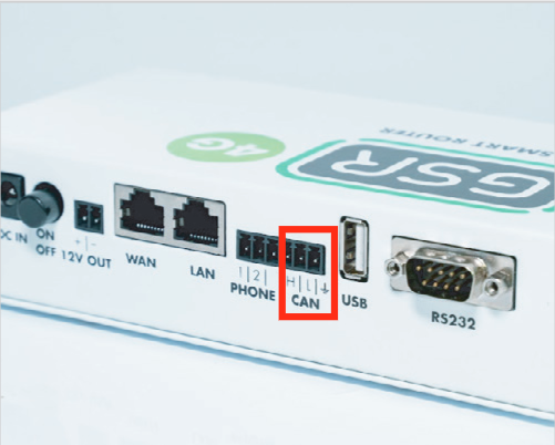
2. Connection
1. Locate connector PC8 and connect as described:

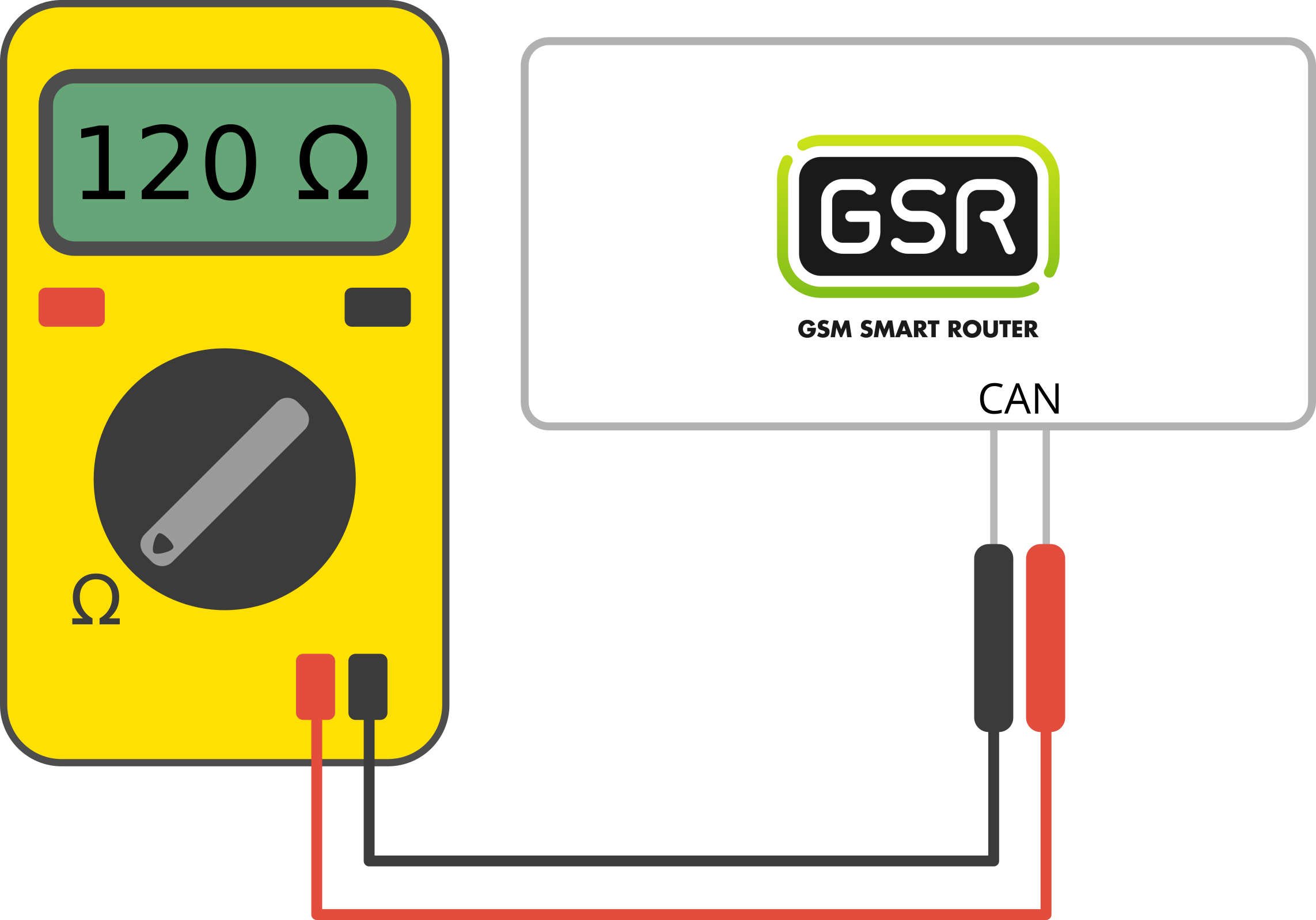
2. Locate the CAN connector on GSR.
3. Make the connection.
| Controller | GSR |
| 1 | H |
| 2 | L |
| 3 | - |
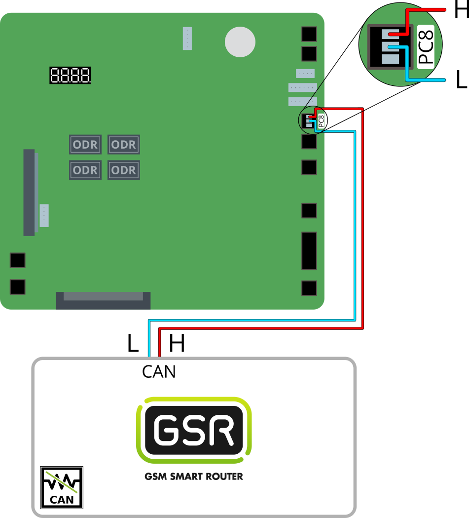 |
Copyright © 2025 Nayar Systems
—
Powered by