1. Required elements
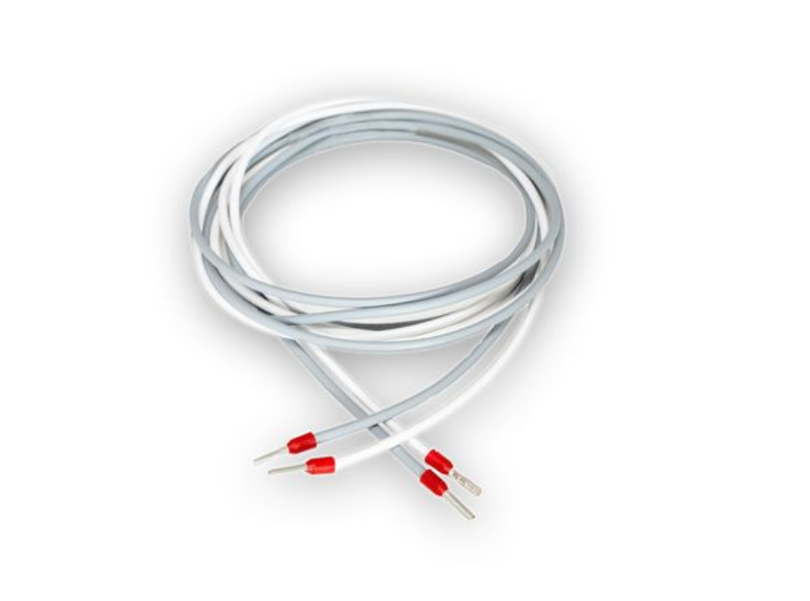
- 2x wires for CAN connection
 |

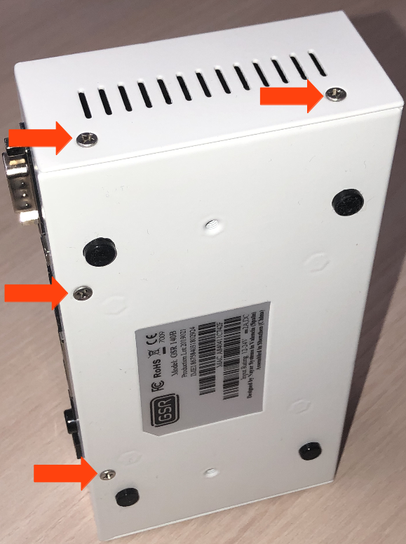
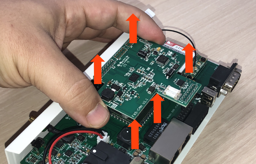
1. Remove the 6 screws from the base and sides
2. Slide the cover until it is removed from the GSR
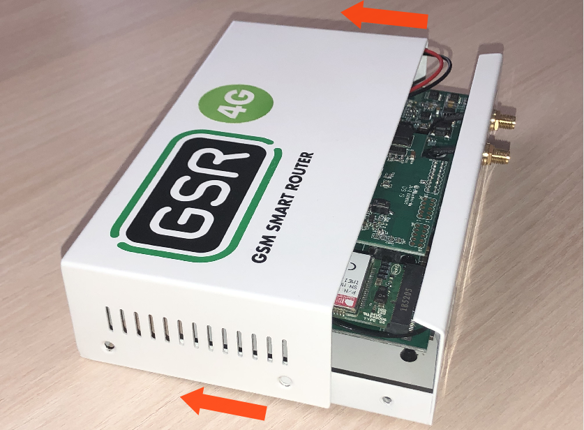
3. Remove the FXS-CAN board pulling gently and equally on both sides
4. Turn around and check that the jumpers are on
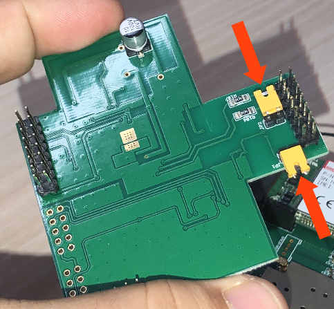 |
5. Remove the jumpers to deactivate the resistors
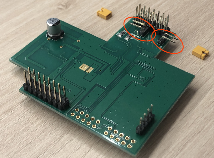
6. Place the FXS-CAN gently, confirming that all pins are aligned correctly
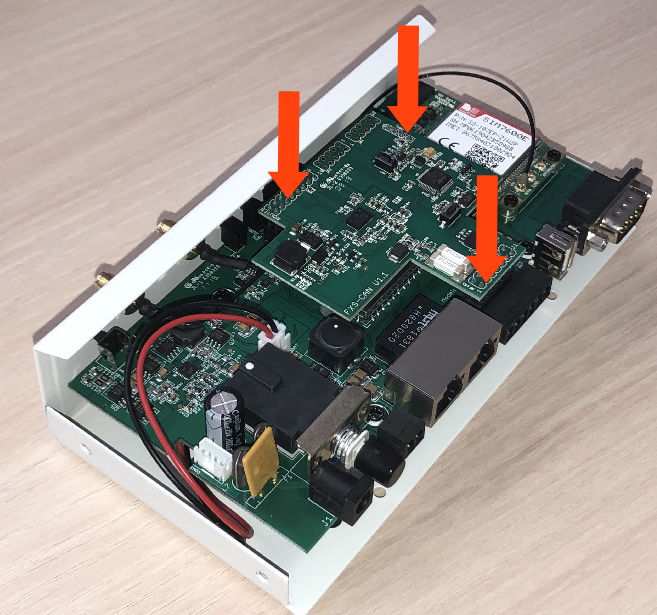
7. Reverse the steps to re-assemble the GSR
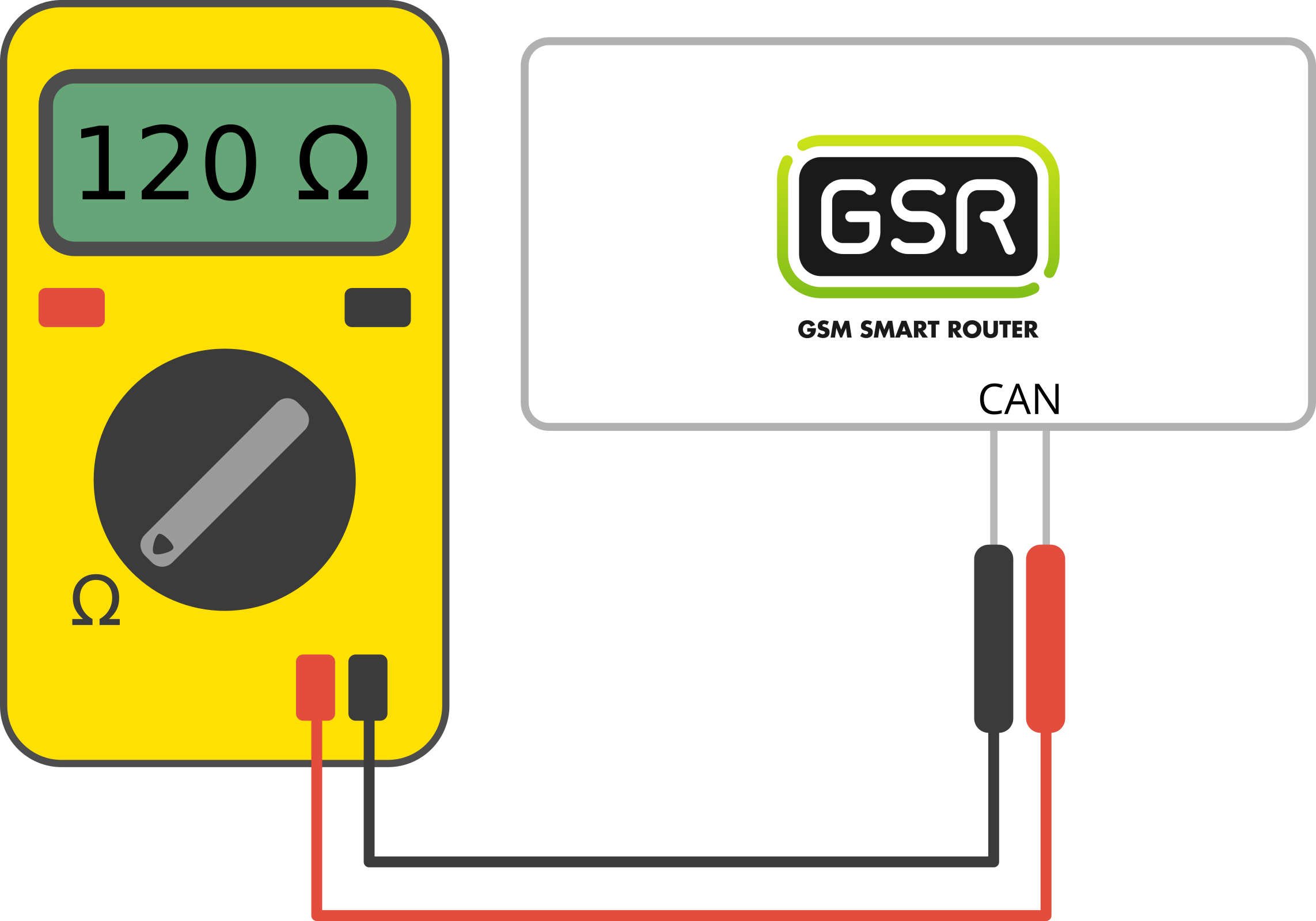
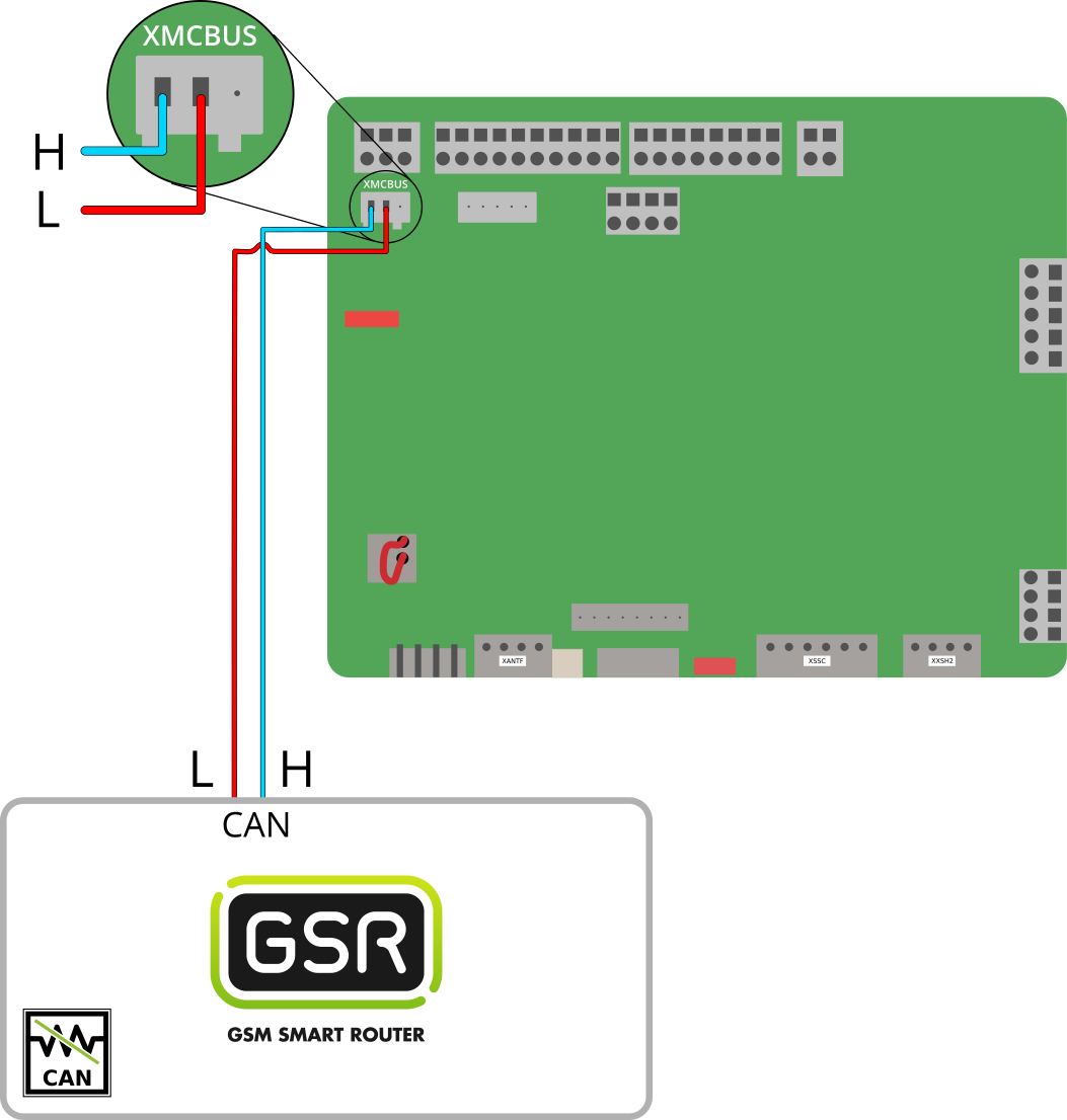
2. Connection
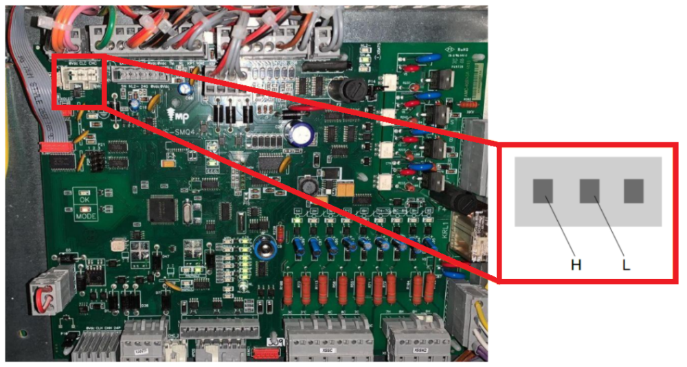
1. Locate connector XMCBUS.
2. Locate CAN connectors on GSR.
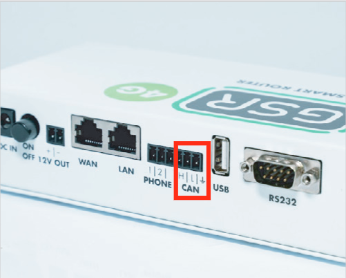
3. Connect as described:
| Controller | GSR CAN |
| CHM | H |
| CLM | L |
 |
Copyright © 2025 Nayar Systems
—
Powered by