TimeMachine Manual
1
1
Table of Contents
TimeMachine Manual
1
TimeMachine Manual — 1
Getting Started
A Quick Look at your TM V3 Reader
A Quick Look at your TM V2 Reader
A Quick Look at your TM V1 Reader
Getting Started – Beginners Overview
Step 1: Charge your Reader
Step 2: Install Timing Software
Step 3: Configure the Network Settings on your Timing Computer
Step 4: Connecting Your Timing Mats
Step 5: Turning on the Reader
Step 6: Getting Tag Reads into Tinyscore
Precautions for Use
Streaming Live Data from the Reader
Via Ethernet
Via WiFi
Via Radio Modem
Via Micro USB Cable
How to disable driver signature enforcement under Windows 8 and 8.1
Finishlynx/Trident Setup Information
Timing Mats
Ultra/Hyper Mat Configurations
Active Loop Configuration
Care of Mats and Storage
Retrieving Data from your TM Reader
FTP Connection
Checking/Setting Reader Date & Time
Clearing Reader History
Understanding the Front Panel of your Reader
Battery Voltage Indicator
Power Button
Radio Antenna
Auxiliary 12V Output
External Power Socket
Receive Loop Sockets
Transmit Loop Sockets
Trigger Socket
Buzzer and Buzzer Socket
RS232 Data Port
Reset Connector
Relay Connector
Clock Connector
Inhibit Connector and Plug
Router Indicators and WIFI
3G Modem USB Socket
Radio Indicators and Reader Status Indicators
Micro SD Card
Transmit Tune Button
Micro USB Socket
Data Mode Switch
Data USB Socket
Receiver Status Indicators
Bluetooth Indicator
Ethernet RJ45 Socket
Status LCD Display
27.1. Network Settings
27.2. Logging Settings
27.3. Data Port Settings
27.4. SD Card Information
27.5. Control Port Settings
27.6. Transmit Status
27.7. Transmit Tuning
27.8. Last Tag Information
Tag Reader Activity Indicator
Configuration Options
General configuration and identity
Logging destinations
Network setup
Router options (for units with X in the product name)
Tag settings
Trigger options
General transmitter settings
DF Transmitter options
UHF options
HTTP Post setup
Command Port Communications
Quick Guide on how to Time an Event
Tag Data Message Format
Extended Trigger Message
Trouble Shooting
Pre-event Checklist
Post Event Checklist
Battery Life
How do I know the Time Machine is Fully Charged?
How to change internal coin cell battery
Optional Accessories
Trident TagScan
Trident TinyScore
Introduction
Reader Setup Tab
Tag Registration Tab
Registration Report Tab
Timing Point Tab
Live Tag Data Tab
Overall Results Report Tab
By Group1 Results Report Tab
By Group1 & Group2 Results Report Tab
By Group1, 2 & 3 Results Report Tab
USB Registration Reader Driver
TimeMachine Firmware Update
Firmware change log
Download as PDF
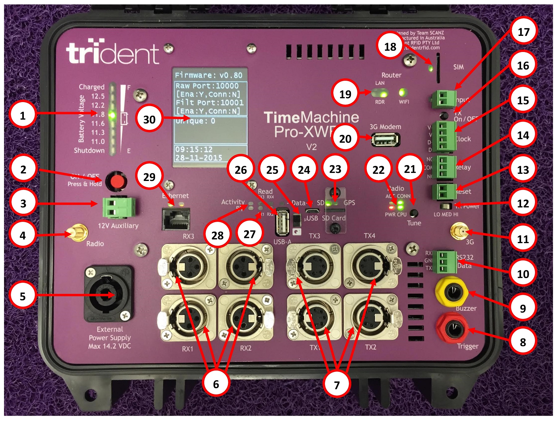
A Quick Look at your TM V2 Reader
Below is a quick explanation on the front panel layout of your TM V2 Reader. Detailed explanations can be found by clicking on the appropriate label in the text below the picture.
1 – Battery Voltage Indicator
2 – Power Button
3 – Auxiliary 12V Output
4 – Radio Antenna Connector
5 – External Power Socket
6 – Receive Loop Sockets
7 – Transmit Loop Sockets
8 – External Trigger Socket
9 – External Buzzer Socket
10 – RS232 Data Port
“11 – 3G Antenna Connection
“12 – TX Power Switch Low, Medium, High
13 – Reset Connector
14 – Relay Connector
15 – Clock Connector
16 – Inhibit Connector
17 – Inhibit Plug
“18 –
SIM
Card
19 – Router Indicators
20 – 3G Modem
USB
Socket
21 – Transmit Tune Button
22 – Radio Indicators
23 – SD Card
24 – Micro
USB
Socket
25 – Data Mode Switch
26 – Data
USB
Socket
27 – Receiver Status Indicators
28 – Tag Read Activity Indicators
29 – Ethernet RJ45 Socket
30 – Status
LCD
Display
To avoid risk of damage or electric shock, ensure the reader and its charger are always protected from rain or splashes of water.
Fully charge the reader’s internal battery before the first use of the reader.
Fully charge the reader’s internal battery before events.
Fully charge the reader’s internal battery after use and prior to storing.
The reader’s internal battery should be fully charged every two months if the reader is not used for some time.
A Quick Look at your TM V3 Reader
A Quick Look at your TM V1 Reader
Was this helpful?
Yes
No
You indicated this topic was not helpful to you ...
Could you please leave a comment telling us why? Thank you!
×
Thanks for your feedback.