
This method allows you to create your own global tags with meaningful names and map them to a specific Word address within a given module. To use this method you will have to be very familiar with the Instance Assembly structure for the ConveyLinx-ERSC Module
Example
In this example we want to read the sensor port inputs and be able to send a clear jam command to the upstream zone on the ConveyLinx module we named feeder in our Topology Example. We also want to read the sensor port inputs and control the left motor on the ConveyLinx module we named workstation in our Topology Example.
Create Tags for our feeder Module
| From Network View, locate the module feeder, right click and select Device configuration and from Device view expand the window from the right to display the Device overview. This will show you the I and Q address byte locations in memory that were assigned when you added the module to you project. As you can see, the feeder module’s I and Q are located in bytes 0 thru 63 respectively. | 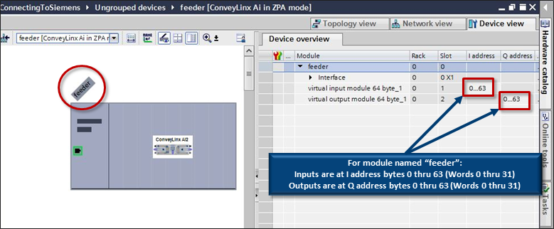 |
We want to read the Sensor Port Inputs register from the feeder module. As shown in the Port Inputs and ConveyStop Status description from the PLC Developer’s Guide section, we can see that the Sensor Port Inputs data is at word register offset 01 within the ZPA Mode assembly instance. To point our new tag to the correct starting byte, we take our word address x 2 to get the starting byte offset address. In our example, this means that the Sensor Port Inputs word register data will be located at I address bytes 36 and 37. When we declare our tag with the W syntax, it will know that the tag requires the 2 bytes beginning at I address 36.
| From our Default tag table, create a new tag and let’s call it feeder_SensorPortInputs. Select Word as the Data type and enter %IW36 for the Address. | 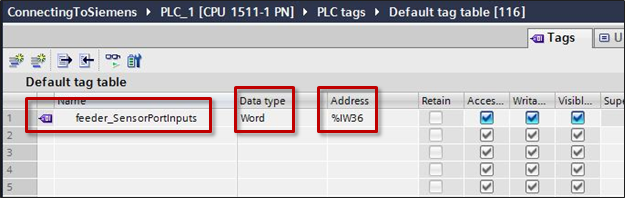 |
We want to write a command to the Clear Jam for Local Upstream Zone register to the feeder module. As shown in the ConveyStop and Clear Jams description from the PLC Developer’s Guide section, we can see that the Clear Jam for Local Upstream Zone data is at word register offset 20 within the ZPA Mode assembly instance. To point our new tag to the correct starting byte, we take our word address x 2 to get the starting byte offset address. In our example, this means that the Sensor Port Inputs word register data will be located at Q address bytes 40 and 41. When we declare our tag with the W syntax, it will know that the tag requires the 2 bytes beginning at Q address 40.
| From our Default tag table, create a new tag and let’s call it feeder_ClearJamUpstreamZone. Select Word as the Data type and enter %QW40 for the Address. | 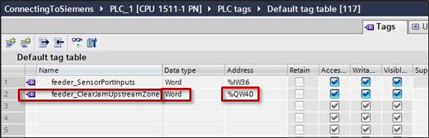 |
Create Tags for our workstation Module
| From Network View, locate the module workstation, right click and select Device configuration and from Device view expand the window from the right to display the Device overview. This will show you the I and Q address byte locations in memory that were assigned when you added the workstation module to you project. As you can see, the workstation module’s I and Q are located in bytes 64 thru 127 respectively. | 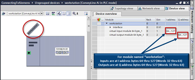 |
We want to read the Sensor Port Inputs register from the workstation module. As shown in the Sensor Ports description from the PLC Developer’s Guide section, we can see that the Sensor Port Inputs data is at word register offset 1 within the PLC I/O Mode assembly instance. To point our new tag to the correct starting byte, we take our word address x 2 to get the starting byte offset address. In our example, this means that the Sensor Port Inputs word register data will be located at I address bytes 2 and 3 within the workstation module. We also need to account for where the workstation module is located within the entire I/O memory. We know that the workstation module starts at %I64 / %Q64, so we need to add our offset of 2 to the starting point of the workstation modules memory. This results in an offset of 66 (64 + 2). When we declare our tag with the W syntax, it will know that the tag requires the 2 bytes beginning at I address 66.
| From our Default tag table, create a new tag and let’s call it workstation_SensorPortInputs. Select Word as the Data type and enter %IW66 for the Address. | 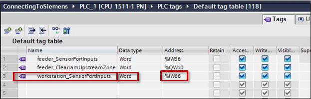 |
We want to write a command to the Left Motor Control register to the workstation module. As shown in the Left Motor Control description from the PLC Developer’s Guide section, we can see that the Left Motor Run / Reverse data is at word register offset 4 within the PLC I/O Mode assembly instance. To point our new tag to the correct starting byte, we take our word address x 2 to get the starting byte offset address. In our example, this means that the Left Motor Run / Reverse word register data will be located at Q address bytes 8 and 9 within the workstation module. We also need to account for where the workstation module is located within the entire I/O memory. We know that the workstation module starts at %I64 / %Q64, so we need to add our offset of 2 to the starting point of the workstation modules memory. This results in an offset of 72 (64 + 8). When we declare our tag with the W syntax, it will know that the tag requires the 2 bytes beginning at Q address 72.
| From our Default tag table, create a new tag and let’s call it workstation_LeftMotorControl. Select Word as the Data type and enter %QW72 for the Address. | 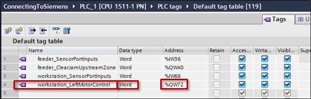 |