These specifications cover ConveyLinx ERSC Hardware Revisions 3 and above and Serial numbers 137101 and higher.
Power Connector
Power connector is included with the ConveyLinx-ERSC Module when shipped from the factory
| ERSC |
Phoenix Contact PN: 1827127 MCVR 1,5/2-ST-3,81 |
| ERSC-HTF |
Phoenix Contact PN: 1912841 MVSTBW 2,5 HC/ 2-ST-5,08 |
Electrical Ratings
| Power supply voltage |
24.0V +/- 10% |
| Standby current consumption |
< 120mA |
| Motor Starting Current |
≤ 5.5A ERSC / ≤ 8A ERSC-HTF |
| Motor Rated Current |
≤ 4A ERSC / ≤ 5A ERSC-HTF |
| Motor PWM Frequency |
10 kHz +/- 0.1% |
Maximum Ratings
!Operating outside these parameters may result in permanent ConveyLinx-ERSC Module failure or unexpected device behavior
| Minimum Operating Voltage |
21V |
| Maximum Operating Voltage |
30V |
| Storage temperature |
-40ºC to 150º C ( -40ºF to 300ºF) |
| Ambient Operating temperature (ERSC) |
0ºC to 40ºC ( 32°F to 104°F) |
| Ambient Operating temperature (HTF) |
-30ºC to 45ºC ( -22ºF to 113°F) |
| Humidity |
5% to 95% non-condensing |
| Vibration |
0.152 mm (0.006 in.) displacement, 1G peak |
| Mechanical Shock |
20G peak for 10ms duration (1.0 ms) |
| Enclosure IP Rating |
IP20 |
| Maximum peak current |
21.5A* |
| Maximum motor start current |
12A |
*This is the maximum current that will be allowed by the hardware over current protection circuitry. On board firmware limits the amount of current based on the quantity and motor types connected
Certifications & Standards
| BDS EN 61131-2:2008 |
Programmable controllers — Part 2: Equipment requirements and tests |
| BDS EN 61000-6-2:2006 |
Electromagnetic compatibility (EMC) — Part 6-2: Generic standards – Immunity for industrial environments |
| BDS EN 61000-6-4:2007 |
Electromagnetic compatibility (EMC) — Part 6-4: Generic standards – Emission standard for industrial environments |
| BDS EN 55016-2-1+A1:2006 |
Specification for radio disturbance and immunity measuring apparatus and methods Part 2-1 Methods of measurement of disturbances and immunity. Conducted disturbance measurements |
| BDS EN 55014-1:2007 |
Electromagnetic compatibility – Requirements for household appliances, electric tools and similar apparatus — Part 1: Emission |
| BDS EN 61000-4-2+A1+A2:2004 |
Electromagnetic compatibility (EMC) Part 4-2: Electromagnetic discharge Immunity test |
| BDS EN 61000-4-3/A1:2008 |
Electromagnetic compatibility (EMC) Part 4-3 Radiated radio-frequency, electromagnetic field immunity test. |
| BDS EN 61000-4-4:2006 |
Electromagnetic compatibility (EMC) Part 4-4 Electrical fast transient/burst immunity test. |
| BDS EN 61000-4-5:2007 |
Electromagnetic compatibility (EMC) Part 4-5 Surge immunity test. |
| BDS EN 61000-4-6:2007 |
Electromagnetic compatibility (EMC) Part 4-6 Immunity to conducted disturbances, induced by radio-frequency field |
| BDS EN 61000-4-11:2006 |
Electromagnetic compatibility (EMC) Part 4-11 Voltage dips, short interruptions and voltage variations immunity tests |
Sensor & Control Port I/O
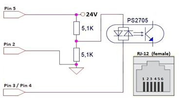
Inputs
| The Sensor and Control port both have 2 inputs each. Sensor and Control port inputs are auto-sensing for the connected circuit type. Input function as either PNP or NPN. Please note that both sourcing and sinking current will activate the input |
![]() |
| Minimum ON current |
1.5 mA |
| Maximum OFF current |
0.4 mA |
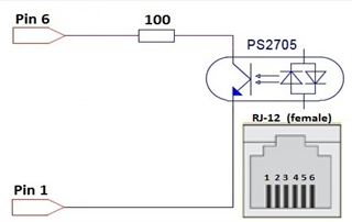
Outputs
| The Control Port output is an NPN transistor whose Emitter (Pin 1) and Collector (Pin 6) are made available to be connected either as sourcing or sinking device in the user’s input circuit |
![]() |
| Minimum ON current |
2 mA |
| Maximum ON current |
8 mA |
| OFF current |
< 100 nA |
Sensor & Control Port Power Pins
Pin 5 of all RJ-12 ports provides 24V for powering up a photo-eye or for biasing the output transistor found on the control port. The current that those pins can supply is limited internally. Each side of the module is fused separately and each side’s control port and sensor port share a solid-state fuse rated at 100 mA. For example, If there is one photo-eye plugged into the left sensor port and one photo-eye plugged in the left control port, then the combined consumption of the two photo eyes must not exceed 100mA.
!Current in excess of 100mA drawn from the sensor port’s 24V pin may cause permanent damage to the sensor detection circuit. Care should be taken to avoid excess loads, short circuits and miss-wiring of the sensor port
Motor Port
| Supported motor types |
3 phase BLDC motors with 3 Hall Effect sensors |
| PWM frequency |
10 kHz +/- 0.1% |
| Maximum starting current |
8A |
| Maximum rated current |
5A |
| Motor Protection* |
Coil-to-coil short, coil-to-Vcc short, overheating, over-voltage, under-voltage, stall sensing and protection |
| Brake output type |
PNP (high side switch) |
| Brake output current |
0.5A (1 A peak) |
!*During normal operation as an MDR port, the internal protection circuitry is not capable of detecting a short-circuit between a BLDC coil output and ground. Such a short-circuit will cause damage to the high-side bridge transistors. When operating these outputs as general purpose outputs, the high-side transistors are disabled, so a pin-to-ground short-circuit is not an issue
Motor Ports in Digital IO Mode as Outputs
Motor Coil Pins 3, 4, & 5
In certain modes of operation (PLC I/O and ConveyLogix PLC), Pins 3,4, and 5 can each be independently switched on and off as general purpose digital outputs. Any individual pin can sink up to 1A to ground in these modes, but the total for all 3 pins combined cannot exceed 1.5A. In general purpose I/O mode, these pins cannot source current.
Brake Output Pin 9
As of firmware version 4.19 and later, the brake output pin can be configured through remote PLC to operate as a general purpose output even if an MDR is connected to the port. This situation requires a special cable or break-out board to be used and the MDR in use cannot have and internal mechanical brake, as that mechanical brake requires a connection to pin 9 for proper operation. The brake-output pin 9 is a 24V high side switch (PNP) that can source up to 0.5A continuously and 1A peak.
Ethernet
• 3 port integrated switch ( 2 external ports and 1 port for the on-board processor)
• Automatic speed setup (10Base-T / 100Base-TX)
• Automatic duplex configuration (Full / Half)
• Automatic straight/crossover cable detection ( Auto MDI/MDI-X)
• PAUSE frame support
• Back pressure flow control support
• Maximum segment length: 100m / 328ft
Supported Protocols
• Modbus/TCP
• EtherNet/IP
• Profinet IO