
A typical situation for using an SE breakout Module is to connect a PLC’s digital output to one of the ERSC’s input signals for interlock control. Some solid state digital output circuits for some PLC models can provide false inputs to the ERSC module because of the module’s PNP/NPN auto-detection circuitry. Some PLC solid state digital outputs can provide an electrical path to ground when powered off. This can result in the ERSC module’s NPN auto-detection circuit to interpret this condition as a positive NPN signal and thus energize its input circuit. The SE Breakout module provides jumper selectable diodes in order to block this opposite flow in order to keep from false triggering an ERSC input.
Both the P3 and P4 inputs on the SE Breakout Module has a pair of user removable jumpers to allow configuration to block a ground path when connecting a PNP input signal and to block a voltage when connecting an NPN input signal.
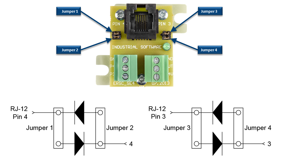
Examples
For a solid state PLC output module SOURCING 24V:
For P4 – remove Jumper 1 and leave Jumper 2 installed
For P3 – remove Jumper 3 and leave Jumper 4 installed
For a solid state PLC Output module SINKING 0V:
For P4 – remove Jumper 2 and leave Jumper 1 installed
For P3 – remove Jumper 4 and leave Jumper 3 installed