
The LINKbridge comes equipped with 4 relays and 4 digital inputs to enable easy control options, without the need for additional hardware.
Example applications:
- Connect a light switch to a digital input and use Routines to trigger a relay output to turn a switch on
- Connect a relay output to a master switch to turn all your 24VDC systems on and off
- Link an output alarm from a device to a digital input and use Alerts to trigger an alarm in LINK
- Link a device trigger to a digital input to receive on/off status notifications inside of LINK
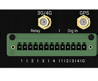
Wiring Information
The digital inputs on the LINKbridge use a shared common connection. It is important to make sure all connections to the LINKbridge are appropriately fused to avoid damage to the device. Digital inputs and relays are rated for 12-24VDC. LINK recommends the use of a 1A fuse on supplies to protect the system and 1-1.5mm tinned marine grade cable. Best practice would also be to install a DC/DC isolator for 12/24VDC supplies in order to prevent noise or surges being generated from other equipment.
Relay Configuration
The relays on the LINKbridge can be customised to better suit your specific application and to remove the need for additional hardware. The relays can either function individually (4 x SPST relays) or they can be grouped to create 2 x DPDT relays. This is configured in the GPIO tab under Tools & Diagnostics on the LINKbridge (http://mylink.local). Please ensure that you have followed all the steps under the Getting Started section of this manual before configuring I/O.
Post your comment on this topic.