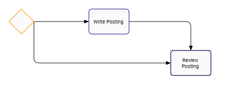
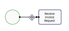
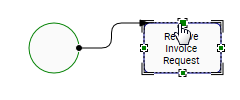
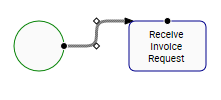
Web Modelers can connect flow objects in a proper sequential order to have a process flow. The transition flow leaves from a source shape to a target shape.
A Target shape can have one or many incoming flows:
A Source shape can have one or many outgoing flows:
We recommend using BPMN 2.0 rules to map processes and connect shapes.
To Connect Shapes, please follow the instructions.
- Navigate to Full Screen Edit Mode, after clicking on Edit Button
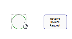
- Click on the Source shape (left-click on mouse). In this example, the start shape is “Start Event”
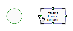
- Drag out the flow (left-click hold) to the Target. In this example, drag the flow from the “Start Event” to the “Task: Receive Invoice Request”
- The task shape will now have target port points (green squares). Connect the transition flow to the target port you desire.
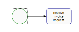
- Release the flow, once you dragged the flow to the target port
To Change the Direction of the Flow Shape, please follow the instructions
- Click on the shape you want to start the connection (left-click on mouse). In this example, the start shape is “Start Event”
- Drag out the flow (left-click hold)
- To change the direction of the flow to the left, move the mouse to the left
- To change the direction of the flow to the right, move the mouse to the right
- To make a break in the direction of the flow, left-click on your mouse and choose the new direction

- Make another flow break, and drag the flow to the task “Update Invoice”
To Change the Source/Target Port, please follow the instructions
- Navigate to the transition flow
- Navigate to the source/target port represented with a black circle. In this example, navigate to the target port in the task
- Drag the target port to another port holding left-click on the mouse. The other ports will be green squares on the shape
- Drop the flow on the new target port
To learn how to optimize the route of the Flow, navigate to the Reroute a Flow section
Haben Sie noch weitere Fragen?
Visit the Support Portal


