
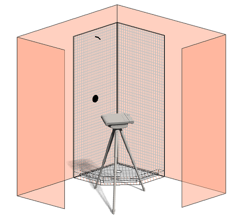
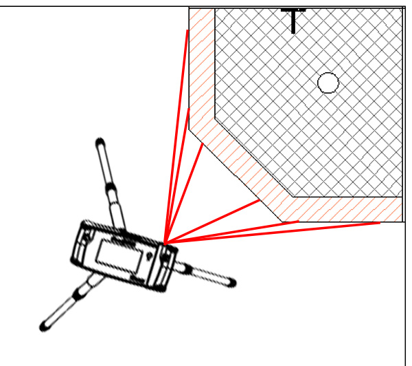
In this example, we will measure the curb to determine the glass position. Then, we will create the 3 folders for the 3 planes of glass, and measure the relevant elements.
- Set up your Flexijet in a position where as much can be measured as possible.
![Shower glass measurement example 1]()
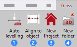
- Auto-Level Flexijet, Align to object, and create a project folder.
![FlexiCAD ribbon with Auto Levelling, Align to Object, New Project, and New Folder highlighted]()
Then, create a horizontal folder, setting the plane on the curb/threshold. This will be a plan view/curb view folder used to plan the placement of the glass.
![Setting plane on curb]()
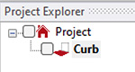
The project explorer should show the curb folder with a horizontal plane established.
![Project Explorer showing Project and Curb folder]()
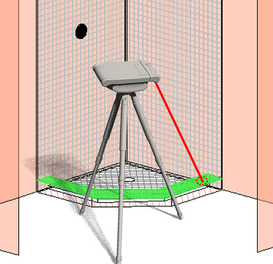
- Measure the outline of the curb/threshold. Note: If the curb/threshold is on multiple levels, it can still be measured in the same horizontal folder – this folder exists only to determine the position of the shower glass panels.
![Flexijet measuring curb for shower glass]()
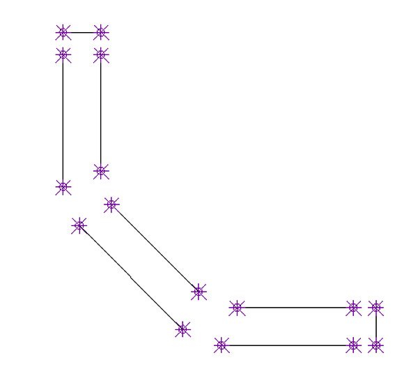
The result should look something like this (measurement points turned on for clarity, and corners not yet connected)
![Curb measured from top viewed in FlexiCAD]()
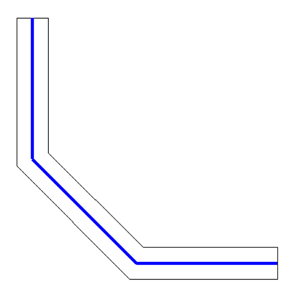
- Decide on the placement of glass on the threshold. In some cases.the glass may be centered on the curb, or inset a particular distance from the outside edge. Glass position is drawn here in blue.
![Software view curb from top with glass position in blue]()
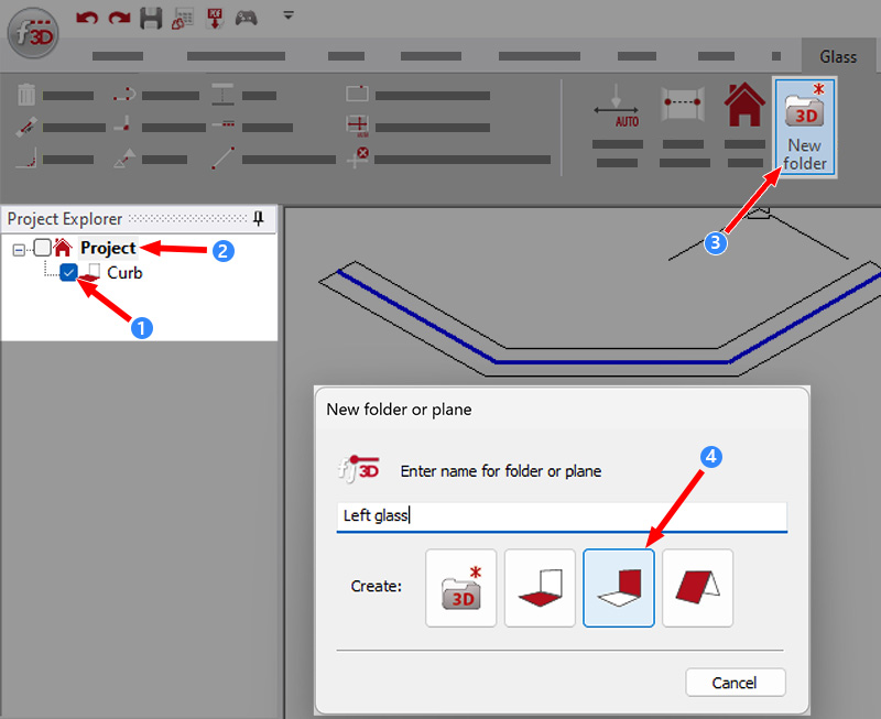
- Now, Create a new folder with a vertical plane. Turn on the checkbox to the ‘Curb’ folder, then Right-click on the Project folder to choose ‘New Folder’ (or use ‘New Folder’ button on the ribbon), select Vertical plane.
![FlexiCAD software view creating folders for glass]()
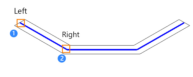
- Following the Command window, Click Left and Right on the glass placement lines in the plan view folder to set the desired plane.The vertical plane will extend plumb vertically from the 2 points setting the plane.
![Diagram showing setting plane on shower curb]()
![]()
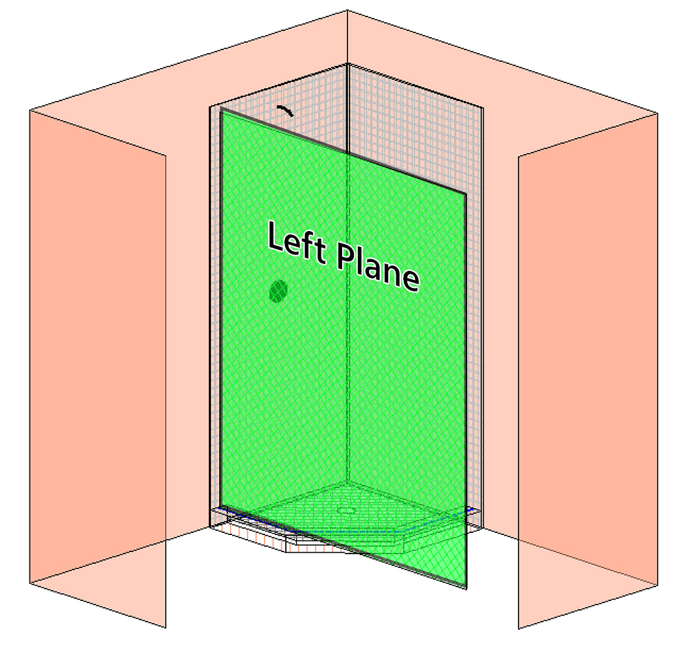
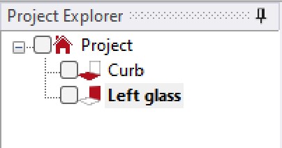
- Uncheck the ‘Curb’ folder. In the new vertical folder, begin measuring where the shower glass will intersect the walls, curb, and ceiling (if needed). Recommend using polylines for surfaces with varying contours.
![Project explorer showing Left glass folder active]()
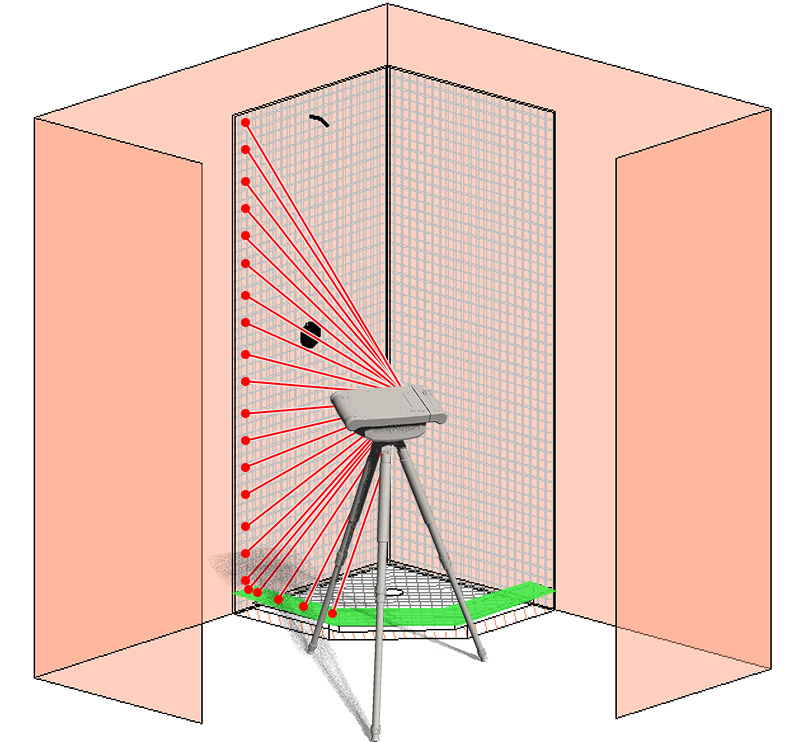
![Flexijet measuring left plane of glass]()
- Connect the corner(s). Use ‘Show CAD-Point’ to visually verify the corner position (if corners exist – in this example, no corners may yet exist on the middle plane)
![Show CAD point on Shoer Glass corner diagram]()

Repeat steps 5-8 for additional planes of glass.
Verification.
- Step 1 of Verification: Connect corners as needed, and use Show CAD-Point or Show CAD-Point to aim Flexijet at the corners for visual verification.
- Step 2 of Verification: Use the Dimension tools to place measurements on the page, and verify with tape measure.
After measuring all planes, edit using commands such as ‘Extend line to plane’ to find the intersection between planes, and ‘Maximum Tolerance’ to find the best-fit lines.
Feedback
Copyright © 2024 Flexijet GmbH
—
Powered by 
Post your comment on this topic.