TOOLS REQUIRED

  • 5.5 mm hex or socket spanner (included in the kit)
  • Phillips screwdriver
  • Cutter
  • Glass ceramic scraper (included in the kit)

The TCU (black box) will be installed in the upper part of the cabin. To this TCU we will connect:

  • 3G SMA antenna (included)
  • Flat cable with 8 binary input connector to the Binary input connector (included). The other end of this cable should be connected to the P5 connector of the remote station RS14 *
  • HDMI cable (included)


INSTALLATION

STEP 1

Remove all cables leading to the display, the cable coming from the remote remote station will be replaced by the cable with TCU connection at one end.

STEP 2

From the back, remove the nuts from the outer frame (3 nuts).

Remove the back frame screws (2 star screws). Phillips screws). Remove all the electronics, we are left with only the frame.

Remove the nuts from the power supply plate (4 nuts), from the minipc (4) and undo the cables grounding (1), and undo the connection cables to the display (4 connectors).

Position of the nuts::
a. Power supply board
b. MiniPc
c. Display source

Disconnecting the cables from the boards:

a. Display cable by pulling upwards
b. Display source cables by pulling to the side

Remove the PC board and the power supply, we don’t need it.

STEP 3

Remove the 8 spacers and the back plate. You can remove the power supply for the screen (optional).

Remove the nuts from the plate (4 nuts).

Remove the plate, it will be reused later. Remove the 4 separators from the the TFT screen.

Remove the TFT screen.

STEP 4

To remove glass, carefully pass a cutter between the glass and the frame, cutting the double-sided adhesive tape.

Once the glass has been removed, pass the glass scraper supplied in the kit, wipe the frame to remove any traces of adhesive tape.
Make sure that the frame is well cleaned of adhesive.

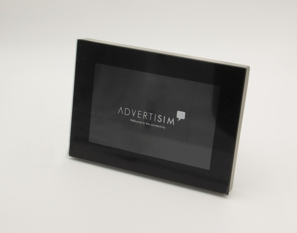
Glue the Advertisim glass to the frame. Pay attention to the centering of the glass in the frame.

At this point it is very important to clean the inside of the glass well, once the TFT screen is in place, it will no longer be accessible. TFT screen will no longer be accessible.

STEP 5

Insert the frame marked with 1 into the bottom of the frame, paying attention to the to the notch, which will be at the top left-hand side. The number should be upwards so that it is legible.

Place the screen in the recess of the frame 1, leaving the black area of the screen at the bottom of the frame. Place frame 2 with the tab in the same position as frame 1. Fit the 4 spacers included in the kit into the MPD pins.

Connect the cable to the TFT screen, by inserting it through the inside of the screen. See the upper part of the connector in the picture.

Mount the frame on the control panel, first fitting its upper screws and then tightening the lower screws.

We will connect to the TFT controller the following cables coming from the TCU located in the cabin roof:
· HDMI cable.
· 12v power cable located above the HDMI connector (not to be confused with the 220v power to 220v or hose).

STEP 6

Mount the display board by passing the TFT cable through the side slot, which will be on the right-hand side.

Fit the 4 long spacers previously removed from the plate itself and place them on the longer pins.

Place the TFT controller on the holes on the spacer pins. The HDMI connector should be facing down and the the display cable over the female pin on the right side.

Screw the plate to the frame, either with the original nuts or with the 4 nuts enclosed in the bag. Screw the large plate to the MPD frame, either with the four spare nuts supplied in the kit or with 4 nuts from the frame itself, which were removed.

Screw the outer frame of the display by screwing it to the TFT screen plate (3 nuts).