VIDEO OF THE ASSEMBLY
COMPONENTS
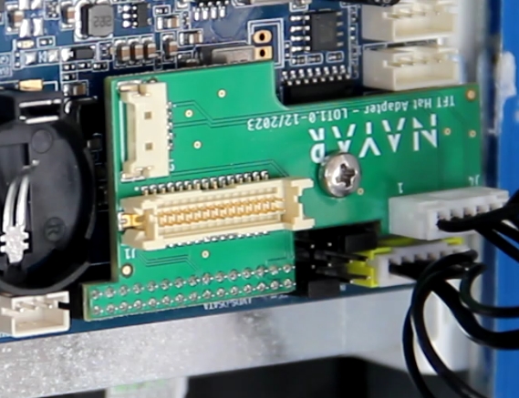
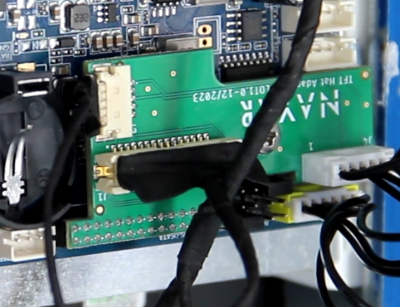
A. Main board
B. GSM antenna
C. Antenna pigtail
D. 12VDC power adapter
E. Connection cable to the RSL
F. Support bracket
G. USBCAN 2
H. Power cord LVDS
I. Adapter TFT OT

INSTALLATION
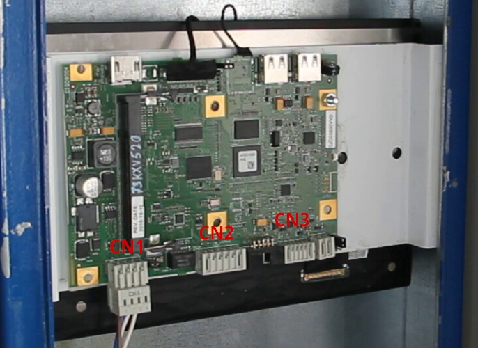
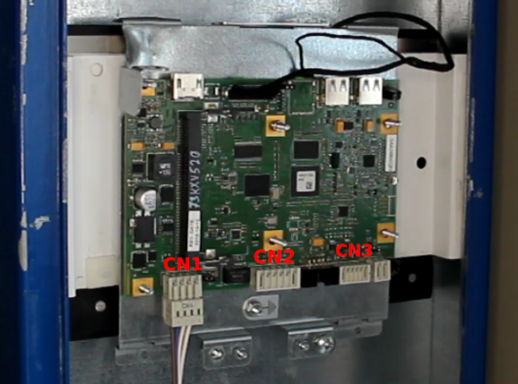
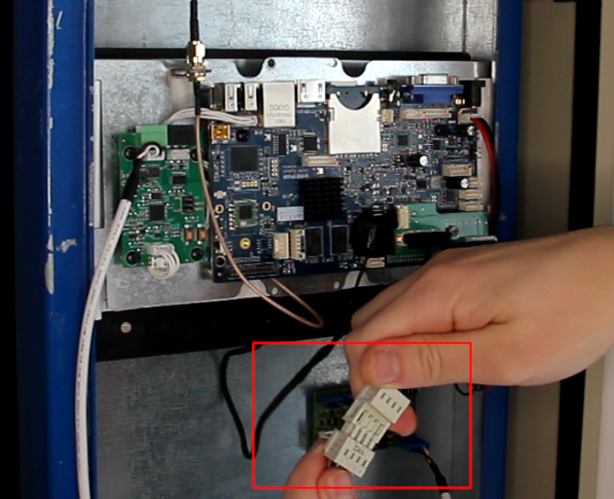
STEP 1: Remove the connections CN1, CN2 and CN3 from the electronics board.
 |
 |
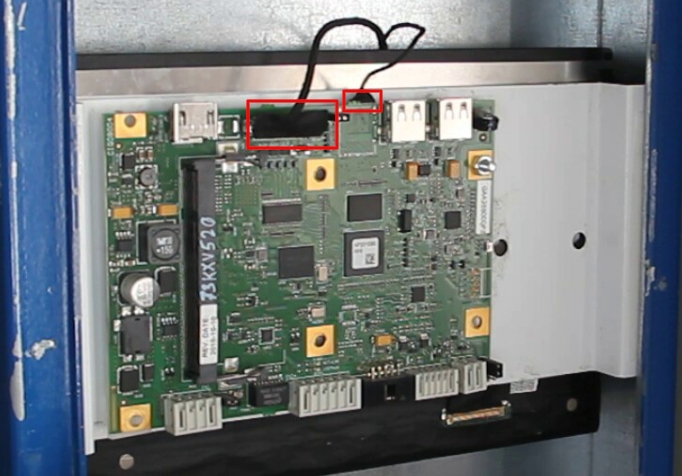
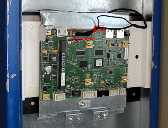
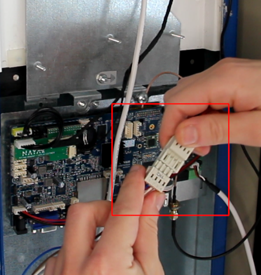
STEP 2: Remove the LVDS and Backlight cable from the electronics board.
 |
 |
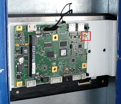
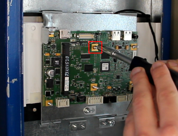
STEP 3: Remove the retaining nuts.
| Flat spanner or number 7 socket (not included) | Number 5.5 cup (not included) |
|---|---|
 |
 |
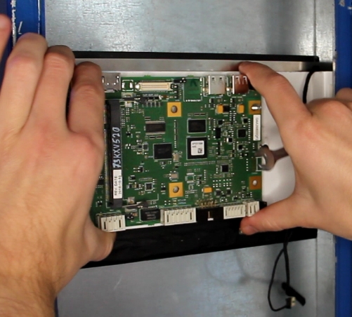
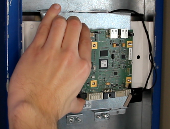
STEP 4: Remove the electronic board from the bracket.
 |
 |
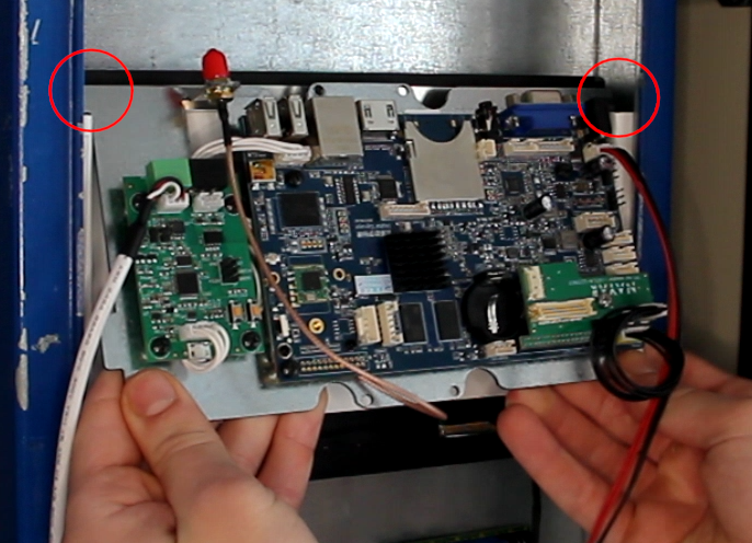
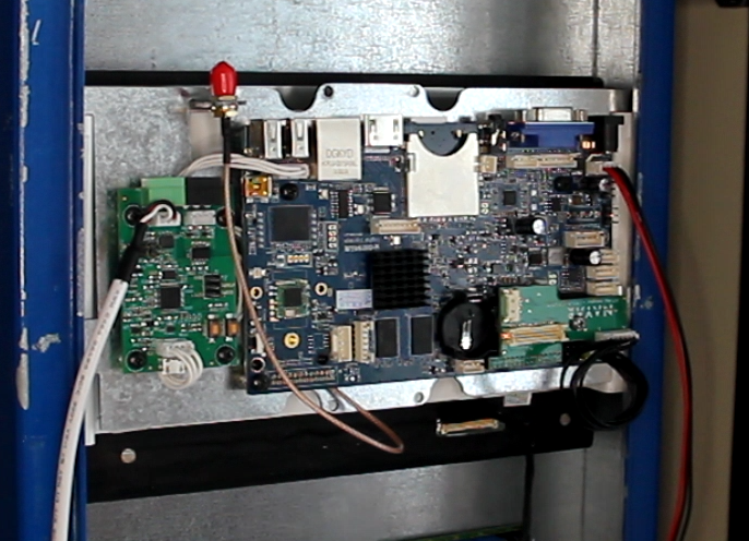
STEP 5: Install the board with the Nayar electronics in the white bracket. To do this, first insert the upper tabs into the side holes and leave the bracket in place. If the silver bracket is mounted, insert the board into the studs and fasten with the nuts previously removed.
 |
 |
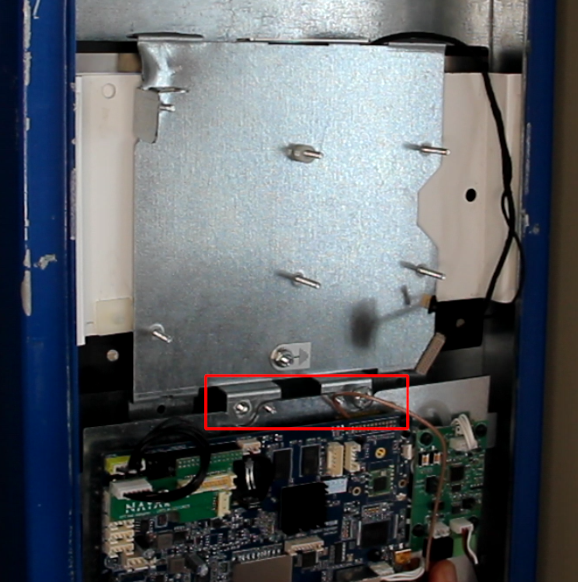 |
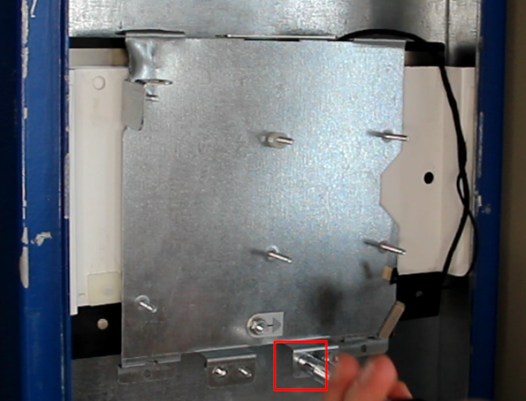
STEP 6: The LVDS and Backligth wiring should be behind the bracket before connecting to the Nayar electronics.
 |
 |
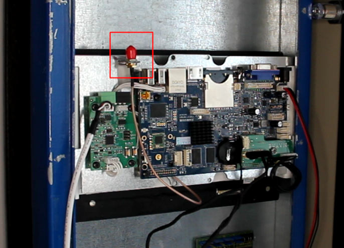
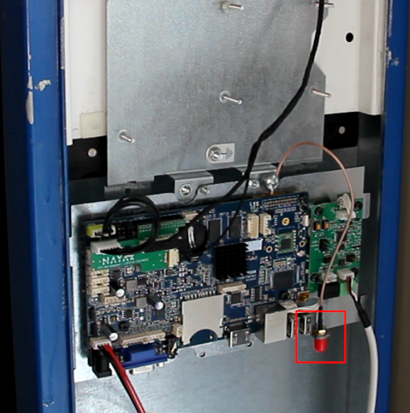
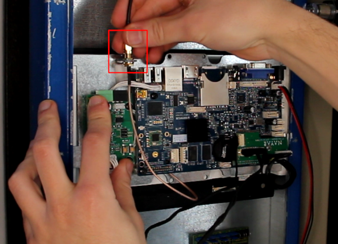
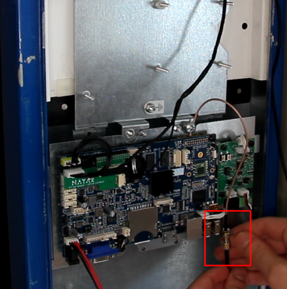
STEP 7: We install the antenna on the roof of the cabin, this is connected to the electronics by screwing it into the terminal protected with a red plastic.
 |
 |
 |
 |
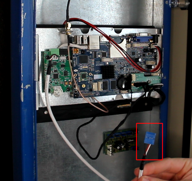
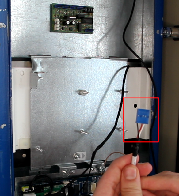
STEP 8: Connect the bus cable to the RSL board.
 |
 |
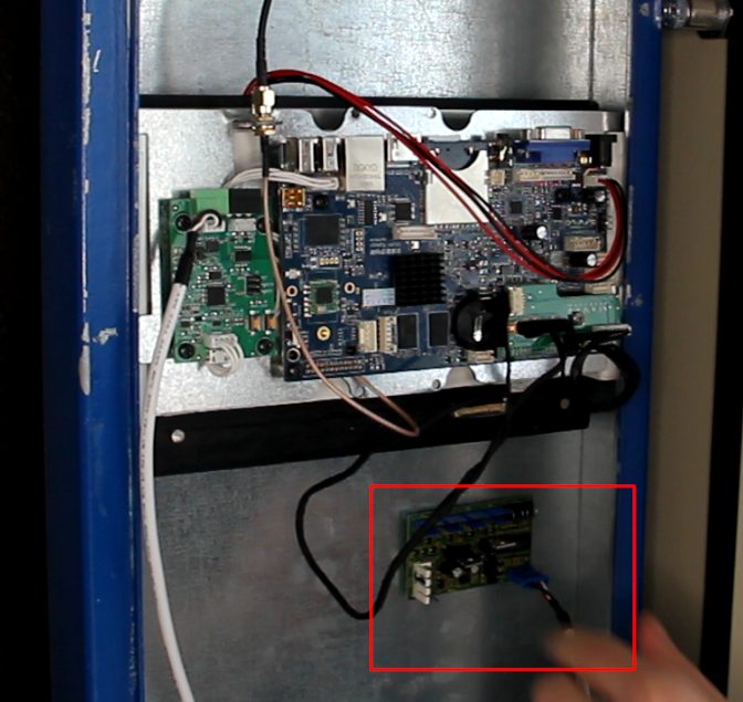 |
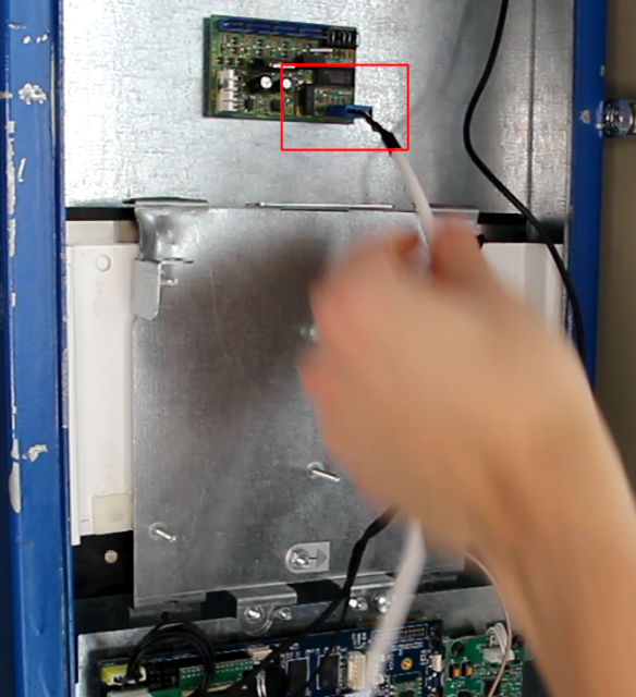 |
STEP 9: Connect the CN1 connector to the display’s power cable.
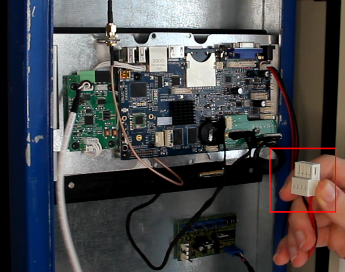 |
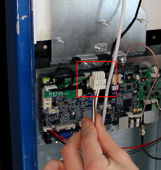 |
 |
 |
STEP 10: Switch on the power supply to turn on the display.