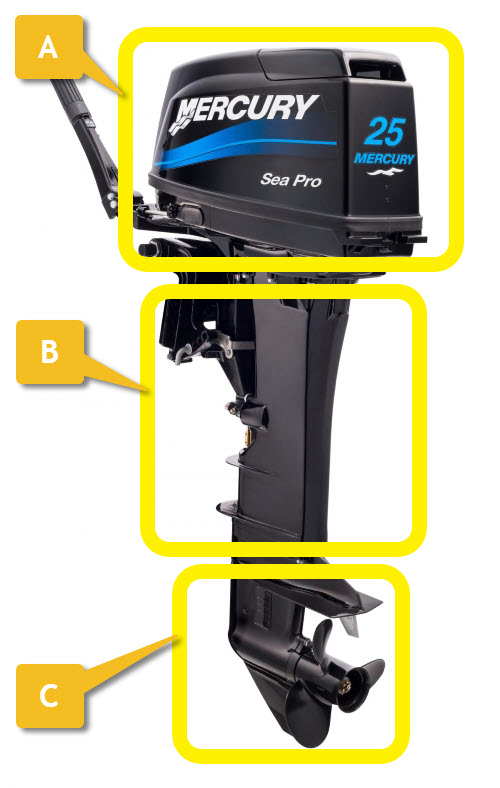
Power head (A)
- The “motor” part of the outboard motor
Leg (B)
- Connects the power head, mounting bracket and steering head to the lower unit.
Lower unit (C)
- Contains the gearbox
- Contains a water pump for motor cooling
- Where the propeller and propeller guard is mounted
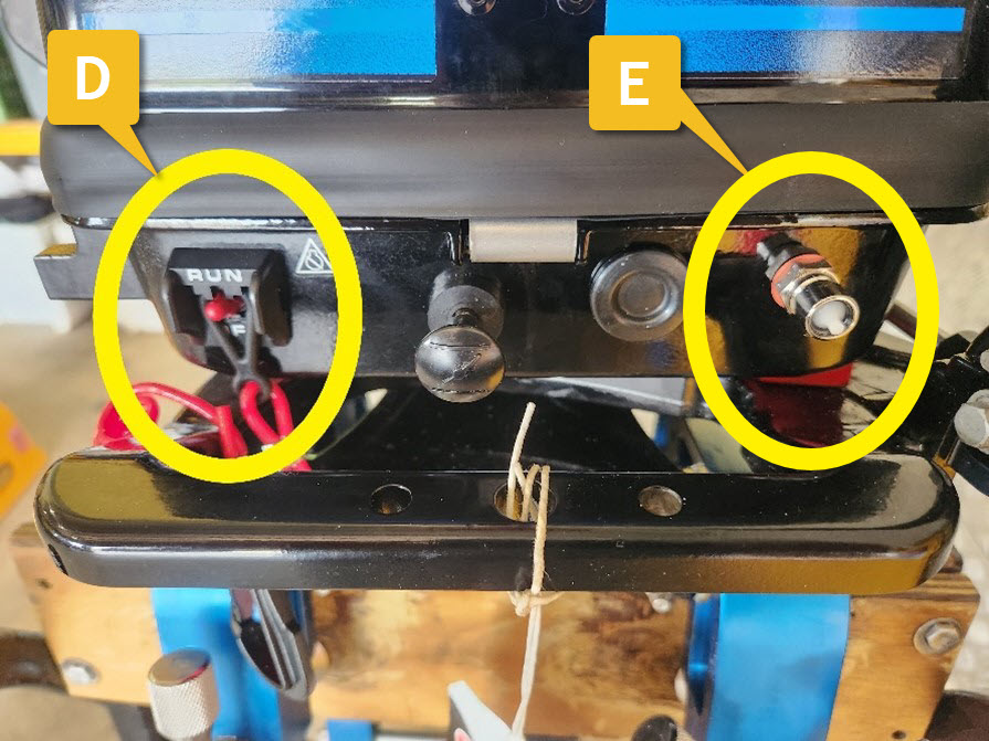
Kill/stop toggle switch and lanyard (D)
- The kill switch disables the ignition system and stops the motor from running.
- The toggle has 2 positions: Run and Off.
- Set the toggle to Run before starting.
Fuel connection (E)
- The flexible hose from the fuel tank connects here and supplies fuel to the motor.
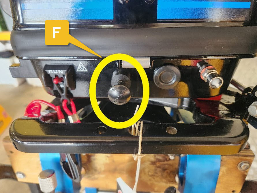
Choke (F)
- The choke on an outboard motor is used to enrich the fuel mixture when starting a cold motor. By restricting the air flow, the choke reduces the amount of air entering the carburettor, which increases the fuel-air ratio.
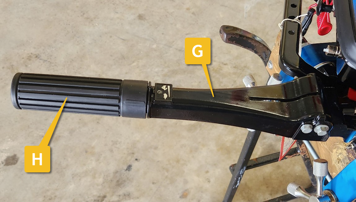
Tiller (G)
- The method by which the motor is moved to Port (left) or Starboard (right) to steer the IRB.
Throttle (H)
- The Tiller incorporates a twist grip throttle control to increase or decrease power.
Motor cowling / cover
- Provides a water and weather resistant cover for the power head.
- Serves as an air intake duct so the motor can run.
- Protects personnel from rotating machinery and electrical systems.
- Provides noise insulation.
- Is attached to the motor via a latching mechanism
- Incorporates motor cowling bungees
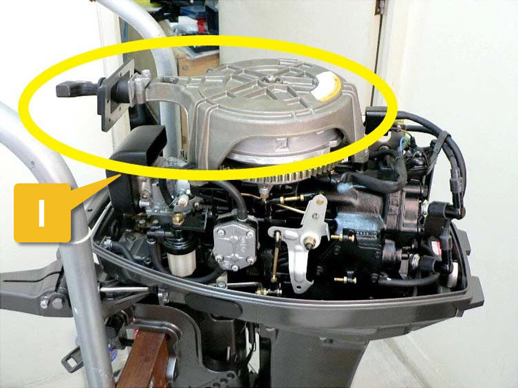
Pull start handle and Recoil starter (I)
- A pull start mechanism on top of the motor. A latch engages with the flywheel to spin the motor and provide initial energy to get the motor running.
- Requires good strength and technique to operate effectively.
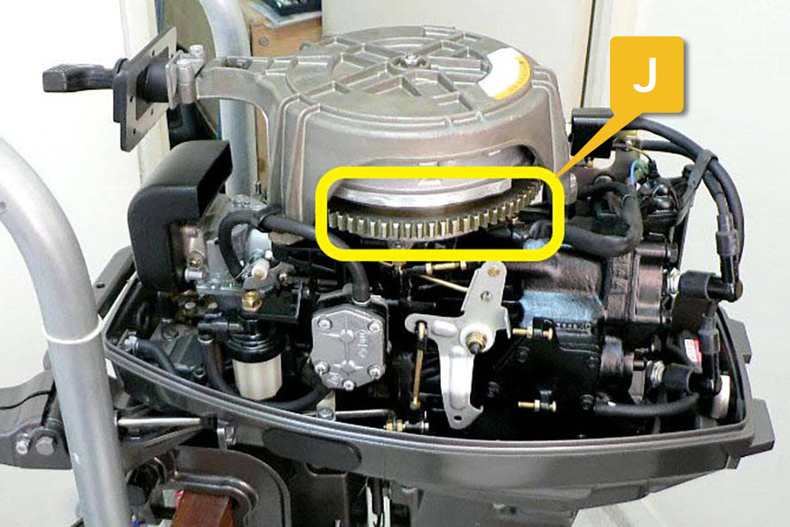
Flywheel and magneto (J)
- Stores mechanical energy to keep the pistons moving at a constant speed.
- Contains magnets which act as part of the ignition electrical system.
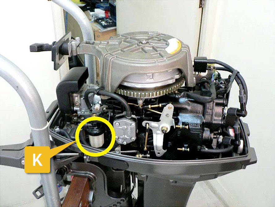
Fuel filter (K)
- Removes contaminants such as sand and water before they are pumped into the carburettor.
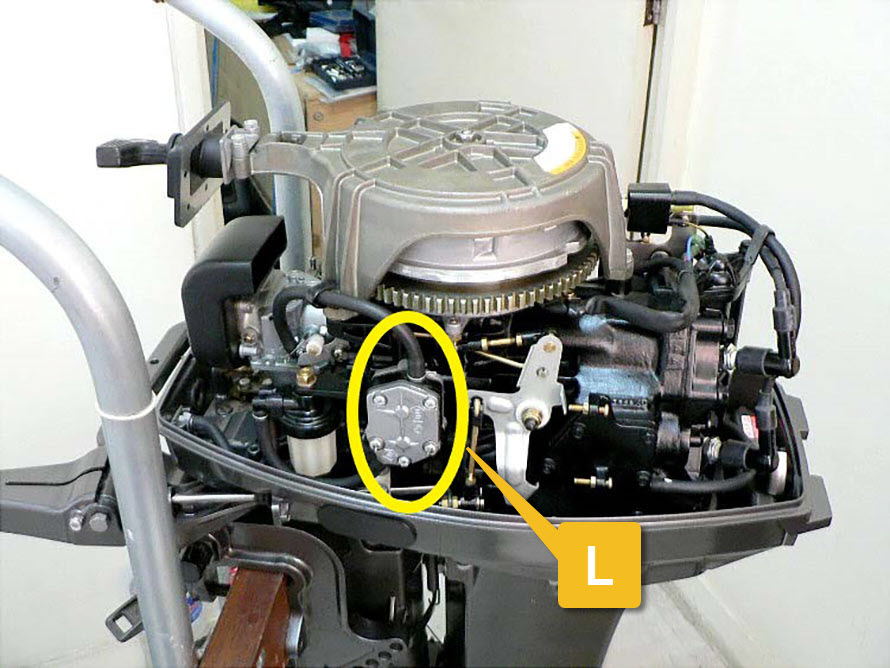
Fuel pump (L)
- Pumps the correct amount of fuel from the filter to the carburettor when the motor is running.
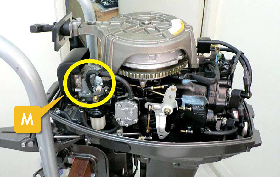
Carburettor (M)
- Receives fuel from the fuel tank, via the fuel hose, motor fuel connector, filter and fuel pump.
- Mixes air and fuel according to throttle position.
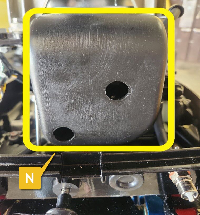
Air box (N)
- Allows a free flow of air into the carburettor.
- Protects the carburettor from large splashes of water.
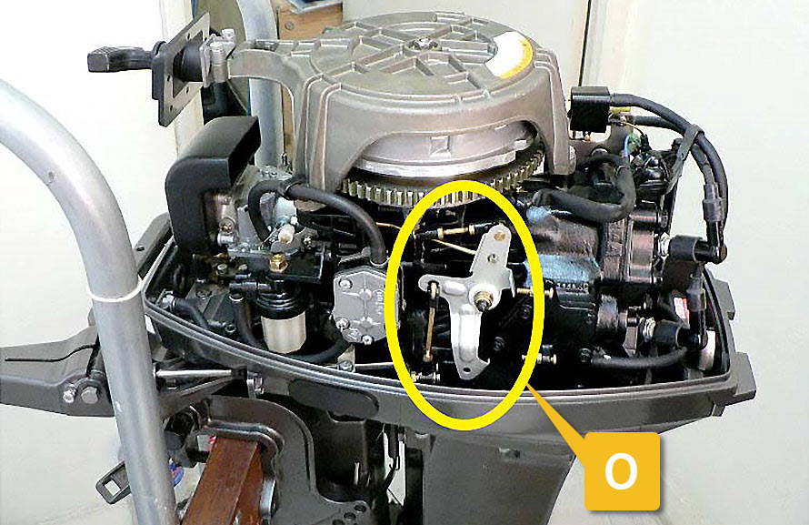
Throttle linkage (O)
- Connects the throttle twist grip control on the tiller to the carburettor and ignition system.
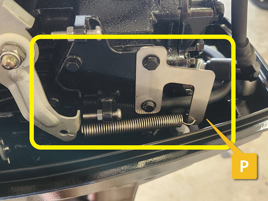
Throttle return spring (P)
- Returns the throttle to idle when the twist grip control on the tiller is released.
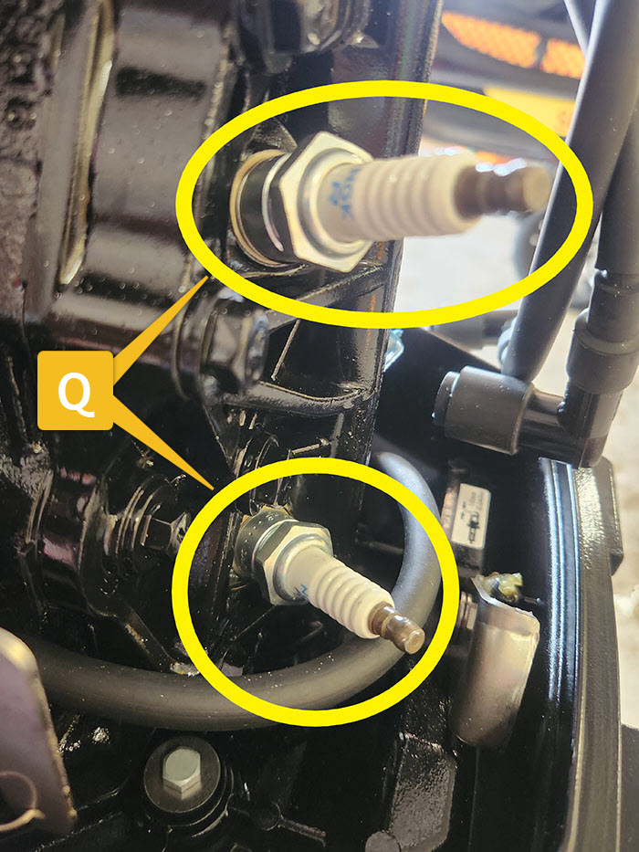
Spark plugs (Q)
- These generate an electrical spark to ignite the fuel / air mix inside the cylinders.
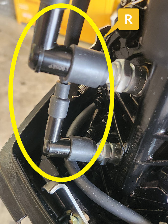
Spark plug caps and high tension leads (R)
- These electrically connect the spark plugs to the ignition coil.
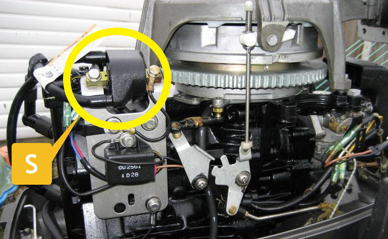
Ignition coil (S)
- This produces the electrical power for the spark plugs to turn into a spark.
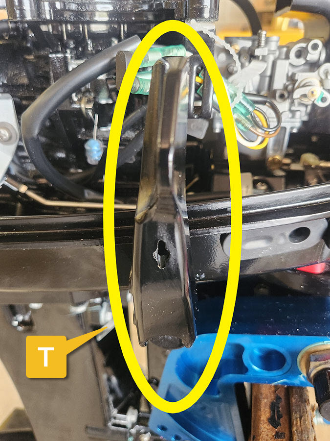
Gear shift lever (T)
- Allows the driver to select Forward, Neutral or Reverse gears.
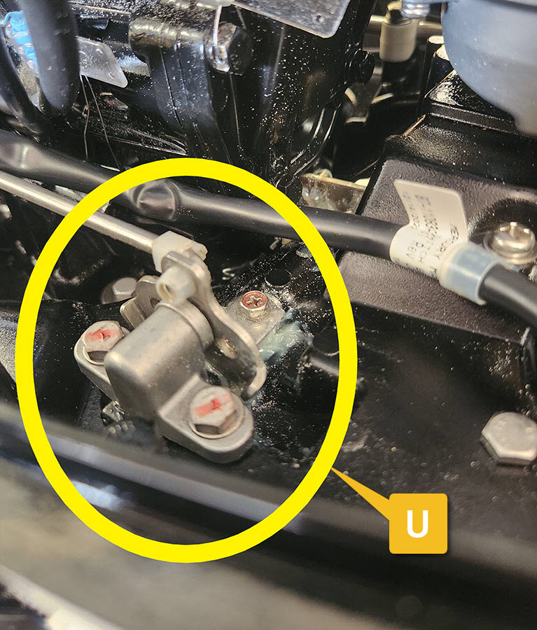
Gear linkage (U)
- Connects the gear shift lever to the internal gear shift mechanism.
Transom mounting bracket (V)
- There are 2 of these. Used for mounting the motor to the transom of the IRB. The one shown is from a surf kit.
![]()
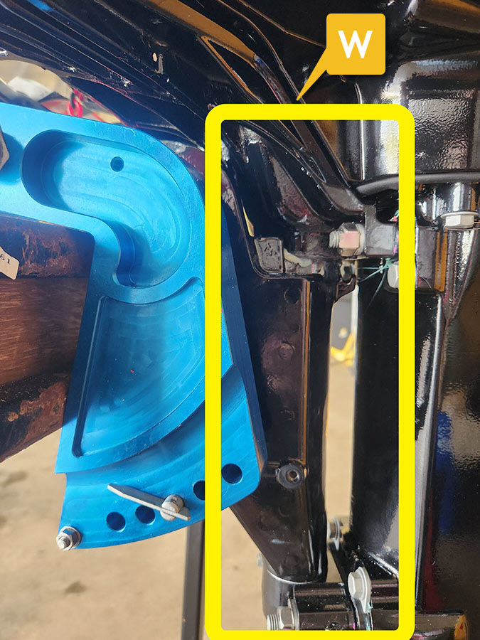
Steering head (W)
- The motor pivots on this solid steel tube, when the tiller is moved, to steer the IRB.
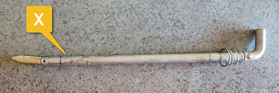
Adjustable Tilt pin (X)
- Located in the row of holes at the bottom of the mounting brackets (see image above)
- Adjusts the angle between the transom for trim.
Tilt tube and nuts (Y)
- Allows the motor to tilt
Transom clamps (Four arm Spin Clamps) (Z)
- 2 of these screws tighten the mounting brackets to the IRB’s transom. The ones shown are from a surf kit.
![]()
Note: Standard transom clamps only have a single arm
![]()
Lower leg
Contains the:
- water pump (1)
- water pickup (2)
- cavitation plate (3)
- gearbox and propeller shaft (4) and
- skeg (5)
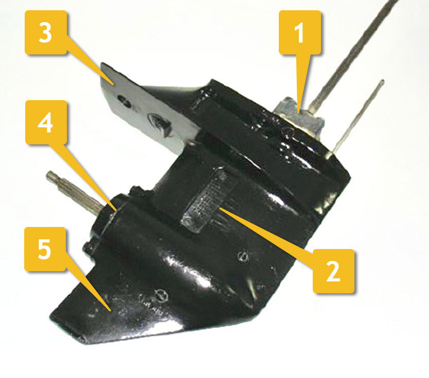
The propeller and propeller guard is attached to the lower leg.
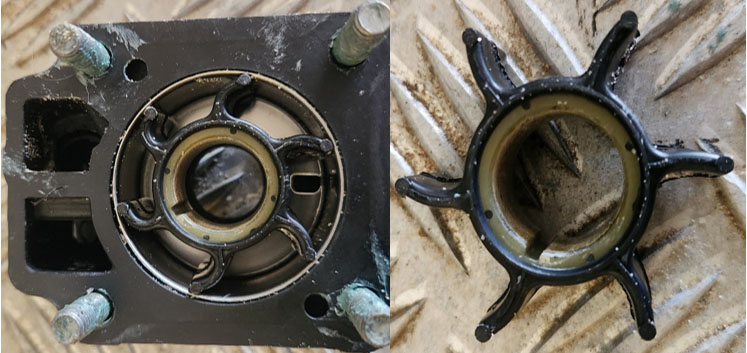
Water pump (1) / Water inlet (2)
- Usually unseen unless the lower unit is removed and is located on the driveshaft at the top of the lower leg.
- A rubber impeller (lower right image) is contained in a housing (lower left) and water picked up via the water inlet moves water up the leg to the power head for motor cooling during running.
Cavitation Plate (3)
- It is a flat, horizontal plate that extends horizontally from the lower unit, just above the propeller.
- The primary purpose of a cavitation plate is to improve the performance and handling of the IRB by reducing cavitation and improving water flow around the propeller. Cavitation occurs when the pressure on one side of the propeller becomes too low, causing water to vaporize and form small air bubbles. This can lead to a loss of efficiency, reduced propulsion, and increased propeller noise.
- The cavitation plate helps mitigate cavitation by redirecting water flow and creating a barrier between the propeller and the water surface. It can increase water pressure on the propeller blades, enhancing traction and reducing the risk of cavitation.
Motor drive shaft, gearbox and propeller shaft (4)
- The driveshaft takes the rotational power from the power head and transmits it to the water pump and gearbox.
- The gearbox changes the direction of the drive and allows the motor drive to be disconnected to the propeller for the selection of neutral and allows for the selection of forward and reverse so as to change the direction of rotation of the propeller therefore changing the propeller thrust direction.
- The propeller shaft connects the motor to the propeller through the gearbox and transmits rotational energy to move the IRB.
Skeg (5)
- keeps the IRB moving straight and protects the propeller and rudder from underwater obstructions.
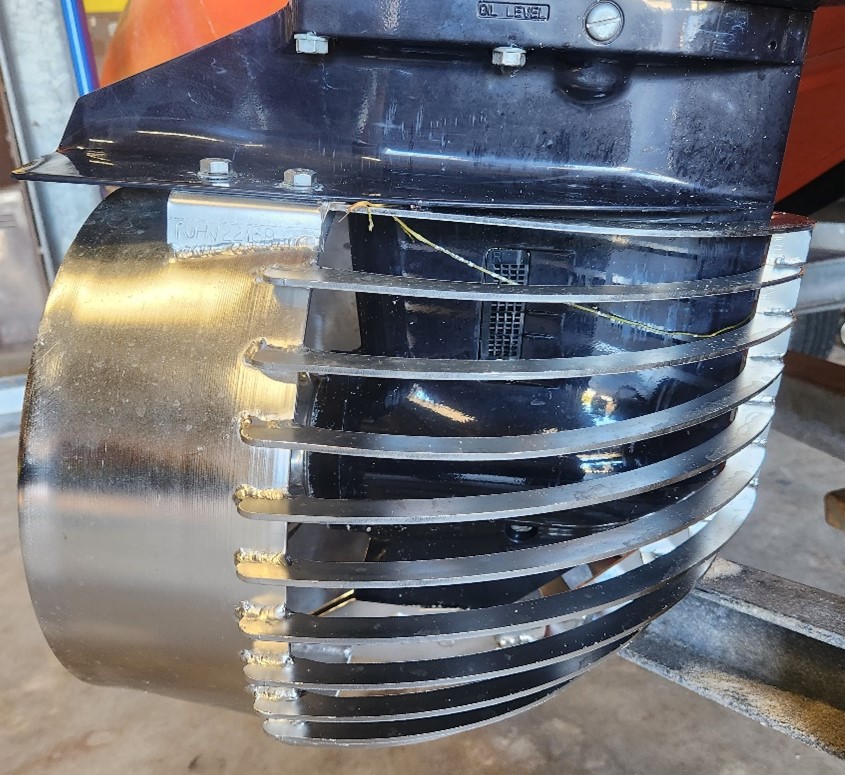
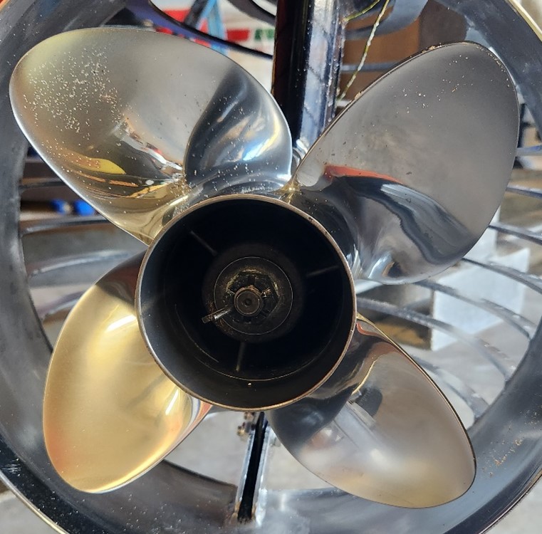
Propeller
- Is attached to the propeller shaft
- Rotates in either direction depending on the gear selected
- Moves water which in turn moves the IRB
- For SLS, it is a 4 bladed stainless steel propeller
Propeller guard
- Protects personnel and marine life from the rotating propeller
- Is attached to the cavitation plate and skeg