
Route twisted-pair cable between the battery and ATevo charger, and make the connections described below BEFORE you move the Remote Sense enable jumpers to enable the Remote Sense feature.
Preparation:
- De-energize and lock out all ac and dc voltages to ATevo.
- Allow internal voltages to dissipate.
- Remove safety shield.
- Verify no hazardous voltages are present with a voltmeter.
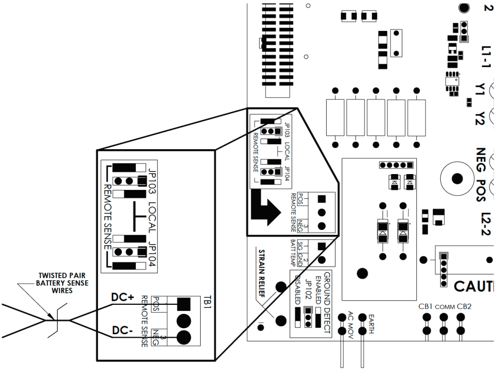
- Route a #16 AWG twisted-pair cable from the bottom of the ATevo Power Board (A2) to the desired battery sense location.
- Designate one (1) wire of twisted pair as ‘DC(+)’ and other as ‘DC(-)’.
- Locate Remote Sense terminal block (A2-TB1) on the bottom front of the ATevo Power Board.
Wiring
- Connect wire from twisted-pair designated as ‘DC(+)’ to the POS (positive) terminal, and connect wire designated as ‘DC(-)’ to the NEG (negative) terminal of TB1.
- Observing correct polarity, connect battery end of ‘DC(+)’ wire to a positive sense location on the battery. Connect battery end of ‘DC(-)’ wire to a negative sense location on the battery.
- Verify your connections.
- DO NOT energize ATevo until you configure Remote Sense jumpers per Section 13.3.
- After Remote Sense Jumpers have been correctly configured, replace the safety shield and re-energize ATevo.
Notes
- Maximum current is 150mA.
- Run the twisted-pair cable with the sense leads in a dedicated conduit.
- Fuse each of the sense wires.
Last modified:
5 March 2021
Need more help with this?
Don’t hesitate to contact us here.