
The Auxiliary I/O Board (A4) requires two (2) hardware configurations:
- the Auxiliary I/O Board Address
- the Binary Input Voltage settings
Auxiliary I/O Board Address
| The ATevo will support up to four (4) Auxiliary I/O Boards (A4). Each Auxiliary I/O Board connected to ATevo must have a unique address setting to identify it to the system. The Auxiliary I/O dipswitch determines the Auxiliary I/O Board Address. |
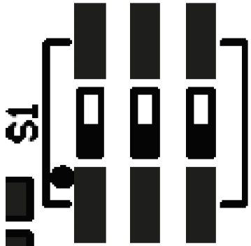 |
The Auxiliary I/O Board address is determined as follows:
- Auxiliary I/O Board #1: 1-ON, 2-ON, 3-ON
- Auxiliary I/O Board #2: 1-OFF, 2-ON, 3-ON
When supplied, ATevo is normally equipped with one (1) or two (2) Auxiliary I/O Boards. However, for special units equipped with more:
- Auxiliary I/O Board #3: 1-ON, 2-OFF, 3-ON
- Auxiliary I/O Board #4: 1-OFF, 2-OFF, 3-ON
The switch setting will be factory set for your system. It should not need to be changed unless an Auxiliary I/O Board is being replaced or added. If a board is being replaced, set the dipswitch settings on the new board to match the board being replaced.
Binary Input Voltage Configuration
Each Binary Input has an associated input voltage configuration jumper. The configuration jumpers (P3, P4, P6, and P7) are located adjacent to the Binary Input Terminal Block (A4-TB1) on the Auxiliary I/O Board. The voltage jumper for Binary Input #1 is shown below.
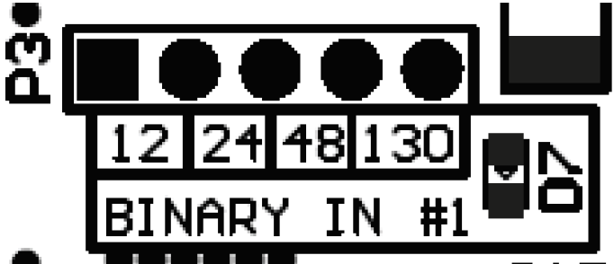
To configure the Binary Input Voltage, move the SHORTING BLOCK to connect the two (2) header pins directly above the voltage rating (12, 24, 48, or 130). Repeat this process for the remaining three (3) Binary Inputs using the associated configuration jumpers for Binary Input #2, #3, and #4.
Need more help with this?
Don’t hesitate to contact us here.