• English
    • Español
ATevo O&SI - 1PH Input Group I (6-25 Adc)
1
  • 1.1
Table of Contents
ATevo O&SI - 1PH Input Group I (6-25 Adc)
  • 1
    • ATevo O&SI - 1PH Input Group I (6-25 Adc) — 1.1
GrabGrab
GrabGrab
  • 1. Receiving & Mounting
    • 1.1. Storing ATevo
    • 1.2. Receiving ATevo
    • 1.3. Unpacking & Inspecting ATevo
    • 1.4. Reporting Damage or Shortage
    • 1.5. Returning Damaged Equipment
    • 1.6. Moving ATevo
    • 1.7. Mounting ATevo
      • 1.7.1. Wall-Mounting (Style-5054)
      • 1.7.2. Floor-Mounting (Style-5054)
      • 1.7.3. Rack-Mounting (Style-5054)
  • 2. Wiring
    • 2.1. Mechanical Diagram
    • 2.2. Removing Protective Safety Shield
    • 2.3. ATevo with Selectable Input Voltage – optional
      • 2.3.1. Determining if Multi-Tap Option is Present
      • 2.3.2. Verifying Multi-Tap AC Input Voltage Setting
      • 2.3.3. Modifying Multi-Tap AC Input Voltage Setting
    • 2.4. Making AC Input Connections
    • 2.5. Making DC Output Connections
    • 2.6. Remote Voltage Sense
    • 2.7. Wiring ATevo Common Alarm
    • 2.8. Wiring Relays on Auxiliary I/O Board
    • 2.9. Wiring Temperature Compensation Probe
    • 2.10. Wiring Serial Communications Adapters
    • 2.11. Wiring Ethernet Adapter
  • 3. Controls & Navigation
    • 3.1. Front Panel Controls & Indicators
    • 3.2. Display
    • 3.3. Main Menu & Navigation
      • 3.3.1. Menu and Arrow Buttons
      • 3.3.2. EDIT/ENTER Button
      • 3.3.3. Navigation Conventions in this Manual
      • 3.3.4. Escape (ESC) Button
  • 4. Startup & Configuration
    • 4.1. Startup
      • 4.1.1. Understanding the Startup Sequence
      • 4.1.2. Factory Settings Tables
      • 4.1.3. Checking Installation
      • 4.1.4. Starting Up
      • 4.1.5. HOME Screen
    • 4.2. Configuring Basic Set Points & Alarms
    • 4.3. Configuring Advanced Set Points & Alarms
    • 4.4. Configuring System Settings
    • 4.5. Configuring Relays
    • 4.6. Disabling Alarms in Common Alarm List
    • 4.7. Configuring Communications Adapters
    • 4.8. Enabling/Disabling High Level Detect
  • 5. Basic Operation
    • 5.1. ATevo Operating Modes
      • 5.1.1. Changing Display Mode
      • 5.1.2. Changing Charge Mode
      • 5.1.3. Changing Equalize Method
      • 5.1.4. Lamp Test & Display of Firmware Versions
      • 5.1.5. Resetting Latched Relays (legacy method)
    • 5.2. High Voltage Shutdown
    • 5.3. Low Level Detect
    • 5.4. High Level Detect
    • 5.5. Disabling Ground Detection
  • 6. Advanced Operation
    • 6.1. ATevo Main Menu
    • 6.2. Alarms Button
    • 6.3. Health Button
    • 6.4. Security & Passwords
      • 6.4.1. Access Security Features & Configure Passwords
      • 6.4.2. Setting Passwords
      • 6.4.3. Setting Default Access
      • 6.4.4. Logging into a Password Authorization Level
      • 6.4.5. Logging Out
    • 6.5. SD Memory Card Features
      • 6.5.1. Installing SD Memory Card
      • 6.5.2. Storing Event Log File to SD Card
      • 6.5.3. Storing/Recalling Settings to/from Memory Card
      • 6.5.4. Upgrading Firmware via Memory Card (v2.6.6 & earlier)
      • 6.5.5. Upgrading Firmware via Memory Card (v2.7.0 onward)
  • 7. Alarms & Indicators
    • 7.1. Legacy Alarms & Indicators
    • 7.2. Common Alarm Indicator & Other Alarm Triggers
    • 7.3. Alarm LED Summary Table
    • 7.4. Viewing Alarms
    • 7.5. Advanced Alarms
    • 7.6. Resetting Latched Alarm Relays
    • 7.7. Battery Open Test
      • 7.7.1. Battery Open Test Settings
      • 7.7.2. Running Battery Open Tests
      • 7.7.3. Resetting Battery Open Alarm
  • 8. Hindle Health System
  • 9. Event Logs
    • 9.1. Viewing Event Log
    • 9.2. Viewing Hindle Health Log
    • 9.3. Clearing Event Logs
    • 9.4. Copying Event Logs to SD Memory Card
  • 10. Battery Temperature Compensation
    • 10.1. Installing the TempCo Option
    • 10.2. Using the TempCo Option
    • 10.3. Temperature Compensation Curves
  • 11. Remote Sense
    • 11.1. Remote Sense Connection
    • 11.2. Remote Sense Wiring Procedure
    • 11.3. Configuring Remote Sense Jumpers
    • 11.4. Disabling Remote Sense
  • 12. Auxiliary Inputs/Outputs
    • 12.1. Auxiliary Input/Output (I/O) Board
    • 12.2. Connections to Auxiliary I/O Board
      • 12.2.1. Wiring Relay Connections
      • 12.2.2. Wiring Binary Input Connections
      • 12.2.3. Wiring Analog Input Connections
    • 12.3. Hardware Configuration
    • 12.4. Software Configuration for Relays
    • 12.5. Software Configuration for Binary Inputs
    • 12.6. Software Configuration for Analog Inputs
  • 13. Forced Load Sharing
    • 13.1. FLS Introduction & System Requirements
    • 13.2. Forced Load Sharing Configuration
    • 13.3. Wiring ATevo Chargers for Forced Load Sharing
    • 13.4. Forced Load Sharing Operation
      • 13.4.1. Requirements to Maintain Forced Load Sharing
      • 13.4.2. Virtual Independent Mode
      • 13.4.3. Forced Load Sharing Alarms
    • 13.5. FLS in Combination with Other Charger Features
    • 13.6. Troubleshooting Forced Load Sharing ATevos
  • 14. Maintenance
    • 14.1. Performing Routine Maintenance
    • 14.2. Ordering Replacement Parts
    • 14.3. Replacing Defective Components
      • 14.3.1. Removing Safety Shield & Replacing Main Control Board
      • 14.3.2. Replacing Communications Adapter Boards
      • 14.3.3. Replacing Rectifier / Heat Sink Assembly or Power Board
      • 14.3.4. Replacing DC Power Supply
      • 14.3.5. Replacing Auxiliary I/O Board
      • 14.3.6. Replacing Filter Capacitor Board Assembly
      • 14.3.7. Replacing AC Surge Suppressor MOV Board
      • 14.3.8. Replacing Eliminator Filter Capacitor – optional
      • 14.3.9. Replacing Circuit Breakers
      • 14.3.10. Replacing Power Isolation Transformer
      • 14.3.11. Replacing Filter Inductors
  • 15. Appendices & Drawings
    • 15.1. Appendix A – Specifications
    • 15.2. Appendix B – Standard Drawings
    • 15.3. Appendix C – Document Control Information
    • 15.4. Firmware v2.7.0 Enhancements
  • 16. Safety Instructions
    • 16.1. Safety Symbols
    • 16.2. Equipment Misuse
    • 16.3. DANGER
    • 16.4. WARNING
    • 16.5. CAUTION
  • 17. Warranty
Download as PDF

3. Controls & Navigation

2.11. Wiring Ethernet Adapter
3.1. Front Panel Controls & Indicators


SECTION TOPICS
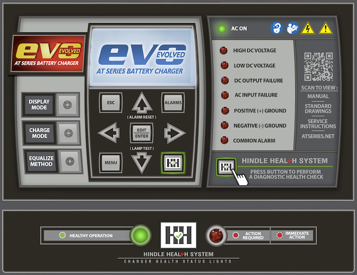
Front Panel Controls and Indicators
Display
Main Menu and Navigation
Last modified: 19 July 2023
2.11. Wiring Ethernet Adapter
3.1. Front Panel Controls & Indicators

Need more help with this?
Don’t hesitate to contact us here.

Thanks for your feedback.
Copyright HindlePower Inc. 2024