An essential part of automating processes involves identifying the proper processes and sub-processes and designing them.
The DBP software enables users both to identify and define the different processes used by organizations and to implement them in the Process Designer module.
When defining a process, the following elements should be documented:
- Inputs
- Outputs
- Roles involved in the process
- Rules
- Operations
- Operational sequence and workflow
- Connection to other processes
- Connection with external information systems
Once they have identified and defined the process (and in doing so, launched the Process Designer), users can use the tools in the Process Toolbox to design the process on the diagram page.
Process Designer Features
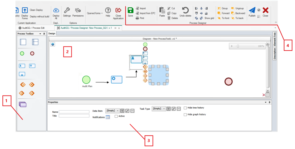
- Toolbox: Here, users can access the elements/flow objects needed to design a process.
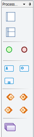
To insert flow objects into the diagram, use the following steps:
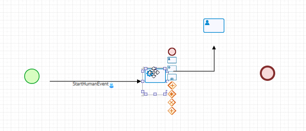
- First, drag and drop the object (event, task, gateway, etc.) from the toolbox onto the design canvas.
- If you have opted for a swimlane diagram, you will first need to drag and drop a pool, then a swimlane, then a flow object before proceeding to the next step.
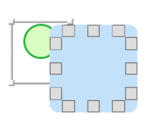
- Next, select the object now situated on the canvas. It will display to its right a list of thumbnails, each representing a different element that the object could be linked to.
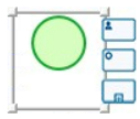
- Select the appropriate thumbnail—that is, the one representing the next object needed for your process—and from the resulting blue field, click on the grey box that most closely aligns with your desired location for the second object.
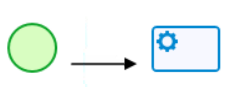
- Once you have determined its location, the second object will appear in the diagram with an arrow linking it to the first object. To modify the position of any object in the diagram, simple select and move as needed.
![]()
- For more details on the Process Toolbox, click here.
- Design Canvas: Here, users can map out their processes.


On the right side of the design canvas, there are two tabs to consider:
- Element Tree Tab
- This tab displays the elements currently being used in the Process Designer. These elements are listed as “Items” (Flow Objects) and “Connections” (Data Flows).

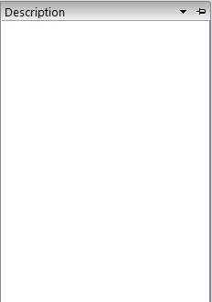
- Description Tab
- In this tab, users can input a description of the process.
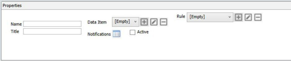
- Properties: Here, users can set the task/flow object properties.
- Whenever a flow object is selected, its properties will appear in this window. Users can then define new information or modify existing information as needed.
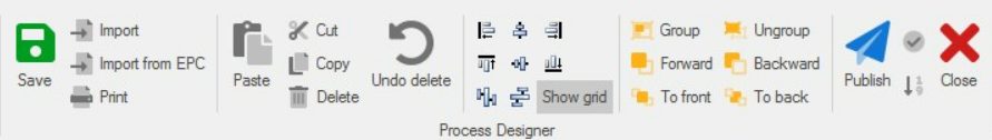
- Menu: Here, users can access other features related to the process design.
- For more details on this toolbar, click here