
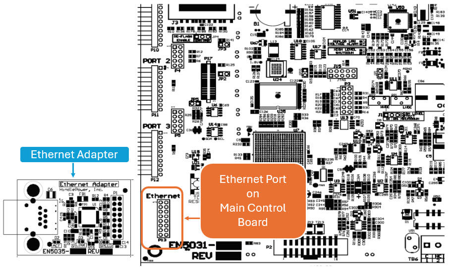
The Ethernet Communications Adapter (A22) plugs into the “Ethernet” port (P13), near the bottom-left of the Main Control Board.
To install an Ethernet Communications Adapter:
- Turn off (open) both AC Input (CB1) and DC Output (CB2) Circuit Breakers.
- Wait for charger voltage to ramp down (display will go blank and all LEDs will be off).
- Open the ATevo front panel door.
- Remove the ground connection from the lower-left corner of the Main Control PC Board (A1).
- Carefully disengage the Main Control Board from standoffs on the left side of the board.
- Locate the Ethernet Communications Adapter connection port (P13), near the bottom-left of the Main Control Board (A1).
- Carefully slide socket (P1) of the Ethernet Communications Adapter onto pins of connection port (P13) of the Main Control Board.
- Hold the Ethernet Communications Adapter (A22) at an angle to clear standoffs on the door.
- Once the Ethernet Communications Adapter socket is fully engaged on the Main Control Board header pins, line up the holes on the Ethernet Adapter (A22) with the plastic standoff pins.
- Press down on the Ethernet Communications Adapter (A22) and the Main Control Board (A1) to lock them onto the standoffs.
- Replace the ground connection on the bottom-left side of the Main Control Board.
- Close the ATevo front panel door.
- Turn on (close) the AC Input Breaker (CB1), then turn on (close) the DC Output Breaker (CB2).
- The Ethernet Communications Adapter hardware is now installed.
- Refer to Section 4.2 to assign protocol and set communications parameters (IP address, Netmask, Gateway, etc).
Last modified:
16 April 2025