This section provides specifics for implementing Modbus protocol via the EPIC Controller Communications. The Modbus protocol was implemented using the Modicon Modbus Protocol Reference Guide PI-MBUS-300 Rev. J.
Supported Function Codes
- 01 – Read Coil Status
- 02 – Read Input Status
- 03 – Read Holding Registers
- 04 – Read Input Registers
- 05 – Read Single Coil
- 06 – Preset Single Register
- 15 – Force Multiple Coils
- 16 – Preset Multiple Registers
Modbus Register Definitions
The following toggles contain tables that identify all the individual registers provided by this implementation of Modbus.
- Modbus Binary Outputs (Coils)
- There are currently no Binary Output registers defined.
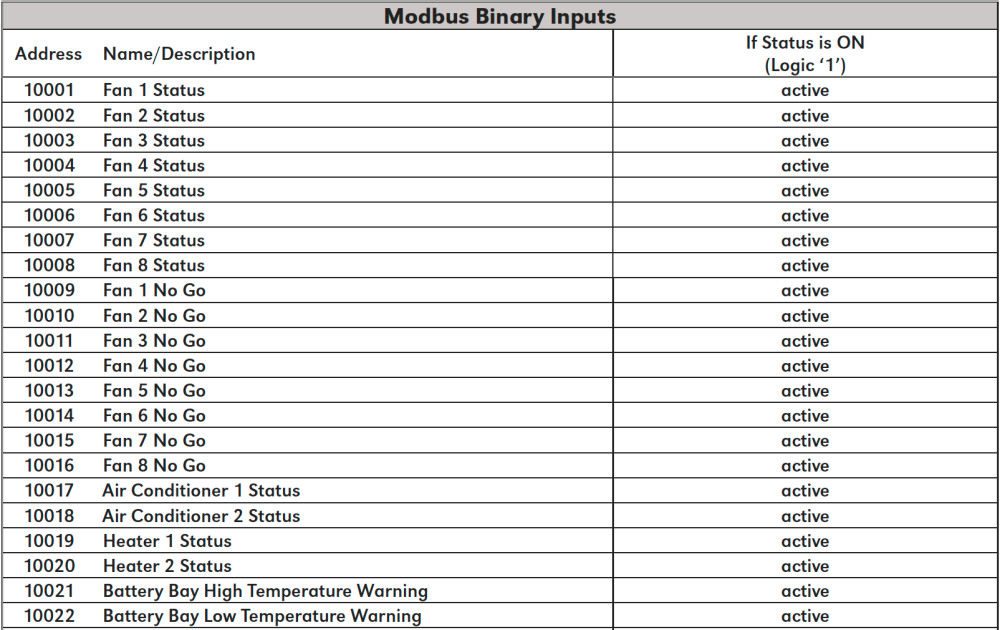
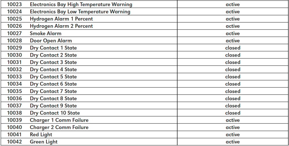
- Modbus Binary Inputs
-
![]()
![]()
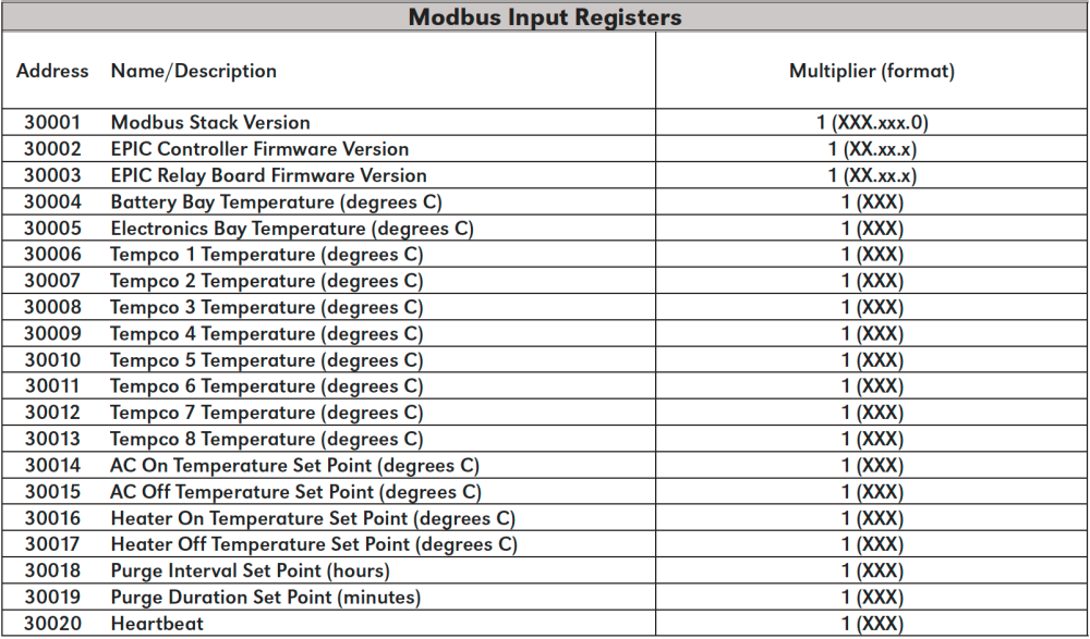
- Modbus Input Registers
- The following table lists the Modbus Input Registers.
![]()
For each point, the “Multiplier” column indicates the value by which the register data are multiplied. Since all data are sent in integer format, floating point numbers are multiplied by a constant (1, 10, or 100) to maintain decimal information. For example, registers with two decimal places of resolution are multiplied by 100 (5.67 is sent as 567) while registers with one decimal place of resolution are multiplied by 10 (8.2 is sent as 82). To convert a register to the correct value, simply divide the register value by the “Multiplier” value.![]()
![]()
![]()
- Upper 8 bits of register value are the Major Version
- Lower 8 bits of register value are the Minor Version
- Example: Version 10.6.0 would be 0×0A06 (hex) = 2566 (decimal)
- Modbus Holding Registers
- There are currently no Holding Registers defined.