
EPIC Console alarms:
- Do not have dedicated LEDs to indicate when they are active.
- Illuminate the RED Hindle Health System LED on the Controller (steady or blinking) and activate the common alarm relay.
- Get stored in the event log along with the time and date they occur, and may be cleared.
- Will be reported to any protocol master polling the Controller.
These alarms are detailed in the toggles found below each of the four alarm categories below:
Communications Failure Alarms
- Relay Board Failure Alarm
- Activate when the Control Board loses communications with the Relay Board.
- Charger Comm Failure Alarm (if installed)
- Activated when communications with connected battery chargers cannot be established or have failed. Alarms from the charger will not display or clear until communications have been reestablished.
EPIC Console Temperature Alarms
- High Temperature Alarm
- Activated when the temperature exceeds the high temperature set point. There is a separate alarm for each temperature probe. The high temperature set points are adjustable.
- Low Temperature Alarm
- Activated when the temperature exceeds the low temperature set point. There is a separate alarm for each temperature probe. The low temperature set points are adjustable.
- Tempco Failure Alarm
- Activated when a temperature probe has failed or reads a temperature outside its designed range. There is a separate alarm for each temperature probe. There are no set points associated with the valid temperature range; the range is a property of the temperature sensor. The HOME screen shows “ − − − “ for failed or out-of-range readings.
EPIC Console Ventilation/Environment Alarms
- Fan Failure Alarm
- Activated when a fan does not spin when power is applied. Each fan is numbered and has a separate alarm. Refer to the console drawings to determine the location of the failed fan, if necessary. There are no adjustable set points associated with fan failure.
Fan failure alarms latch. This means that when there is a fan failure, the alarm will stay active even after the alarm condition has cleared and will require the user to manually clear the latched alarm. This helps avoid the situation of a user not being alerted to intermittent fan failure because the fan happens to be operational and the Hindle Health System GREEN LED happens to be lit while the user is present, even though it failed temporarily while the user was not present. Alarm latching lets the user know that the fan did fail even though it currently is operational and has the green LED lit.
![]()
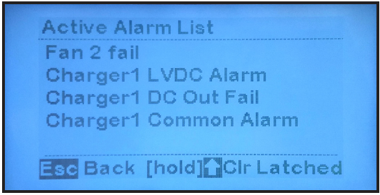
![]() To understand how fan alarm latching works, let’s consider another example. A user notices the red Hindle Health System LED is illuminated, goes to the Active Alarm List, and sees four active alarms. Subsequently, the user replaces Fan 2 which clears the alarm condition. However, because fan failures latch, the RED LED remains lit and the alarm still appears on the Active Alarm List screen. Notice that the “Clr Latched” command appears at the bottom of the Active Alarm List when any of the alarms are latched. To clear the latched alarm, the user must press and hold the UP arrow key on the Alarms List screen. After doing so, only three alarms will remain on the Active Alarm List in this example.
To understand how fan alarm latching works, let’s consider another example. A user notices the red Hindle Health System LED is illuminated, goes to the Active Alarm List, and sees four active alarms. Subsequently, the user replaces Fan 2 which clears the alarm condition. However, because fan failures latch, the RED LED remains lit and the alarm still appears on the Active Alarm List screen. Notice that the “Clr Latched” command appears at the bottom of the Active Alarm List when any of the alarms are latched. To clear the latched alarm, the user must press and hold the UP arrow key on the Alarms List screen. After doing so, only three alarms will remain on the Active Alarm List in this example.![]()
- Hydrogen 1% Alarm
- Activated when the hydrogen detector (optional) detects a level of 1% hydrogen in the battery bay.
- Hydrogen 2% Alarm
- Activated when the hydrogen detector (optional) detects a level of 2% hydrogen in the battery bay.
- Smoke Alarm
- Activated when the smoke detector (optional) detects the presence of smoke in the battery bay.
- Fire Suppression Active Alarm
- Activated when the fire suppression system (optional) discharges. All active HVAC components, including fans, heater, and air conditioner, are shut down to prevent venting of the fire suppressing gas or adding fuel to a fire. The fire suppression alarm is a latching alarm (See Fan Failure Alarm above for an explanation of latching alarms).
- Door Open Alarm
- Activated when the door sensor (optional) detects that the battery bay door is open.
- Air Conditioner Failure Alarm
- Activated when fault signal from the air conditioner indicates a problem.
Charger Alarms (if installed)
- Charger High Voltage DC Alarm
- Activated when: (1) there is a high DC voltage alarm condition on a connected charger, or (2) a charger is in high voltage shutdown. The Alarm screen will indicate which charger has alarmed.
- Charger Low Voltage DC Alarm
- Activated when there is a low voltage DC alarm condition on a connected charger. The Alarm screen will indicate which charger has alarmed.
- Charger DC Output Failure Alarm
- Activated when there is a DC Output Failure alarm condition on a connected charger. The Alarm screen will indicate which charger has alarmed.
- Charger AC Input Failure Alarm
- Activated when there is an AC Input Failure alarm condition on a connected charger. The Alarm screen will indicate which charger has alarmed.
- Charger Positive Ground Fault Alarm
- Activated when a positive ground fault condition is detected by a connected charger. The Alarm screen will indicate which charger has alarmed.
- Charger Negative Ground Fault Alarm
- Activated when a negative ground fault condition is detected by a connected charger. The Alarm screen will indicate which charger has alarmed.
- Charger Common Alarm
- Activated by all alarms from AT10 chargers, and any ATevo charger alarms that have been
configured to activate a Common Alarm. Please see any of the following ATevo operations manuals for instructions on configuring which alarms activate the Common Alarm.
ATevo Operations – Single Phase Input – Group I 6-25 Adc Output
ATevo Operations – Single Phase Input – Group II 30-100 Adc Output
ATevo Operations – Three Phase Input – 25-1000 Adc Output