EPIC Controller Communications has two (2) Serial Communications ports supporting connections to RS-485 networks. Serial ports must be configured correctly before connecting to the network.
RS-485
RS-485 is a standard, defining electrical characteristics of drivers and receivers for use in balanced digital multi-point systems. RS-485 networks can be used effectively over long distances in electrically noisy industrial environments. Multiple devices may be connected to the same network.
Some RS-485 networks may require termination resistors at both ends of the serial network. The decision of whether or not to use termination resistors should be based on the BAUD rate, the cable distance, and the type of cable being used to build the network. In most cases for BAUD rates less than 19.2K, termination resistors are not required. If termination resistors are used, the network must be designed with the appropriate biasing resistors to ensure reliable communications.
Biasing resistors ensure that the network remains in idle state when all drivers are tri– stated. To guarantee that the receivers remain in a known state, +/– 200mV must be maintained across the RS\ 485 inputs, (A) or (–) and (B) or (+). When termination resistors are used, this requires a significantly lower value of biasing resistors which results in greater DC–loading of the network.
Network design and biasing resistor calculations depend on the number of network nodes, the type of drivers and receivers on the network, and any biasing already designed into other devices sharing the network. As a result, termination resistor decisions, and biasing resistor calculations are beyond the scope of this manual. For more information on biasing and termination details see the following references:
- EIA/TIA-485 Standard Telecommunication Industry Association
- RS-422/RS-485 Application Note Copyright: B&B Electronics
2-wire RS-485 Connections
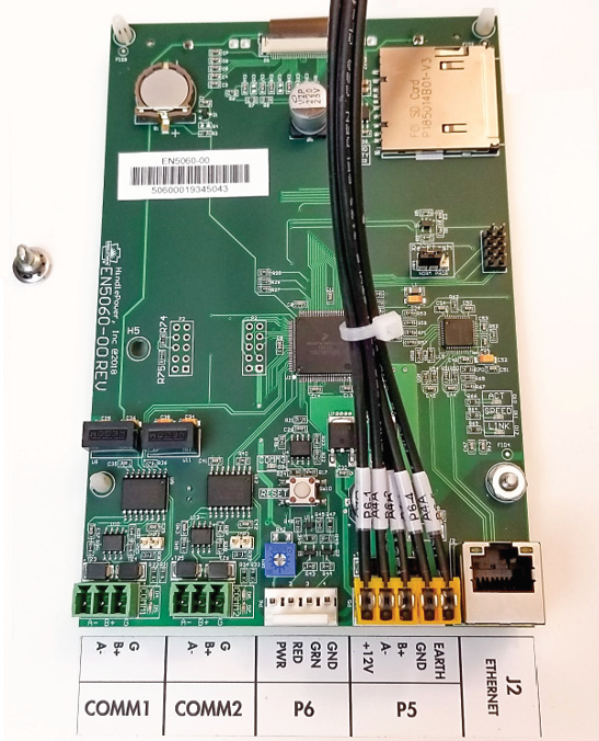
To make connections between the EPIC Controller and an RS-485 network, open the EPIC Controller display door. As seen below, two (2) RS-485 ports are located on the bottom left corner of the EN 5060-00 display board that is mounted in the EPIC Controller enclosure. Attach (A–), (B+), ground(G) to the communication port. Instructions for configuring RS-485 ports are in Section 10.2 of this manual.