
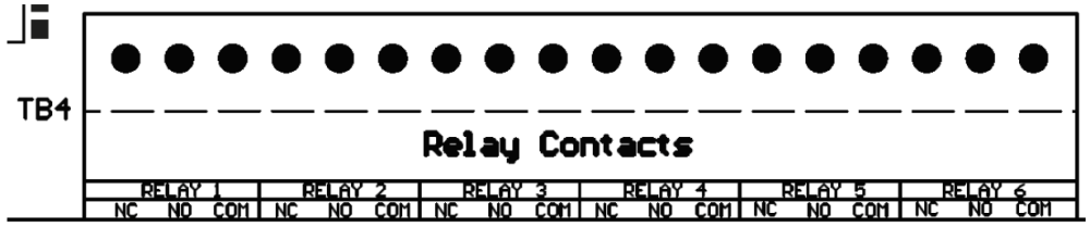
Connections to the relays are made through an 18-position terminal block (A4-TB4). Connections to the six (6) programmable relay contacts are clearly labeled on the board.
Procedure
- De-energize and lock out all ac and dc voltages to ATevo.
- Allow internal voltages to dissipate.
- Remove safety shield and verify no hazardous voltages are present with a voltmeter.
- Route remote annunciator wiring to Auxiliary I/O Board (A4) through an unused enclosure knockout.
- Connect wiring (#22-14 AWG) to appropriate terminals on the Auxiliary I/O Board (A4-TB4).
- Strip each wire 0.25in / 6.4mm, and tighten terminal screws.
- Replace the safety shield and close the front panel door.
- Re-energize ATevo.
Notes
- Alarm contacts are rated at 0.5A @ 125 Vac/Vdc.
- Terminal block (A4-TB4) is compression type, accepting #22-14 AWG wire.
- Terminals are labeled in the non-alarm condition, with ATevo operating ‘normally’ and relays energized.
![]() – not ‘shelf state’
– not ‘shelf state’ - If user alarm contacts (A4-TB4) are to drive inductive dc loads (e.g. a larger dc relay) an external protective diode must be installed at the dc relay to avoid equipment damage. Refer to Application Note (JD5011-00).
 – not ‘shelf state’
Last modified:
21 April 2023