
The Three Phase Input ATevo which has an output range of 75-100 Adc has the following mechanical layout and wiring diagram screen-printed onto its patented, internal protective Plexiglas shield.
PLEXIGLAS SCREEN PRINT IMAGE NEEDED
Click on the name of any individual component for detailed information and a close-up view:
ONCE IMAGE OBTAINED, THESE TOGGLES CAN BE MODIFIED TO MATCH IT
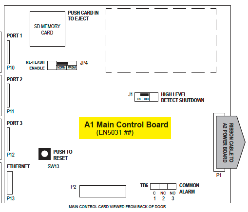
- A1-Main Control Board
- Shown on top-right of silkscreen. Mounted on the ATevo front panel door. Contains display, buttons, alarm indicators, and is responsible for battery charger controls.
![]()
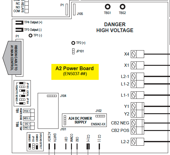
- A2-Power Board
- Shown on bottom-left of silkscreen. Mounted on heat sink along left side of ATevo. Contains most power electronic connections, and terminal blocks for remote sense and battery temperature compensation options.
![]()
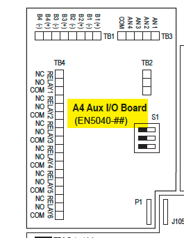
- A4-Auxiliary I/O Board
- Shown at top-left of silkscreen. Bolted to heat sink on the left side, above the Power Board. Plugs directly into Power Board (A2).
![]()
- six (6) relays, four (4) Binary Inputs, and four (4) Analog Inputs
- relays can be configured to indicate status of six (6) different alarms or status points
- independently-isolated Binary Inputs can be configured to report ON/OFF status of four (4) controls
- Analog Inputs include input scaling and can report the status of four (4) analog controls referenced to the dc bus
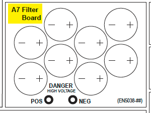
- A7-Filter Capacitor Board
- Shown near top-left of silkscreen. Bolted to top of the Power Board (A2). The capacitors (C1x) filter ‘ripple’ from the dc output.
![]()
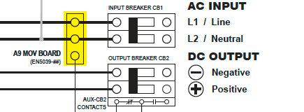
- A9-AC Surge Suppressor MOV Board
- Shown to left of AC Circuit Breaker (CB1) on silkscreen. Mounted to top-left side of breaker bracket. Contains ac input surge suppression and filtering. It is located for easy access, examination, and replacement in case an input transient event should occur.
![]()
- A10-Remote Temperature Probe – optional
- The battery temperature compensation, or ‘TempCo’, probe (A10) contains a temperature-dependent resistor in an epoxy module. When used, this probe is installed on the battery and is connected to the Power Board (A2) at TB8.
![]()
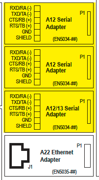
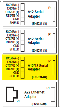
- A12-Serial Communications Adapter
- Shown above Ethernet Comm. Adapter (A22) on silkscreen. Up to three (3) Serial Communications Adapter boards (A12) can be plugged into the Main Control Board (A1) at locations P10, P11, and P12. This option supports DNP3 and Modbus protocols, and can be configured to support 2-wire or 4-wire RS-232 connections, or 2-wire or 4-wire RS-485 connections.
![]()
- A13-Forced Load Sharing Communications Adapter
- Mounted similarly to Serial Communications Adapter (A12).
![]()
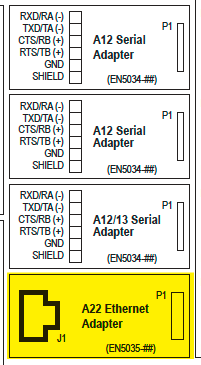
- A22-Ethernet Communications Adapter
- Shown directly to bottom-left of Main Control Board (A1) on silkscreen. Plugs into Main Board at P13. Supports DNP3 and Modbus protocols via 10/100 copper Ethernet connection.
![]()
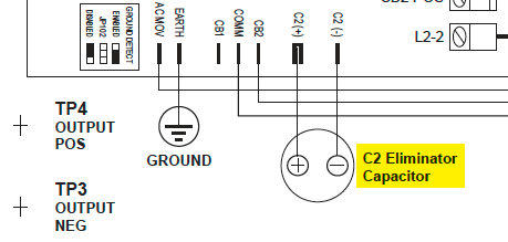
- C2-Eliminator Filter Capacitor – optional
- Shown below Power Board on silkscreen. Mounted on bottom-left under Power Board. Provides the additional ripple filtering, required for the ‘filtered eliminator’ option.
![]()
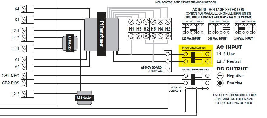
- CB1-AC Input Circuit Breaker
- Located in center of ATevo, about one third from bottom. Protects ATevo ac wiring, and can be used to disconnect from ac source.
![]()
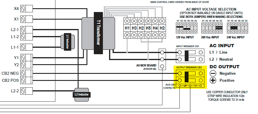
- CB2-DC Output Circuit Breaker
- Located at bottom-center of ATevo. Protects ATevo dc wiring, and can be used to disconnect ATevo from battery and system dc load(s).
![]()
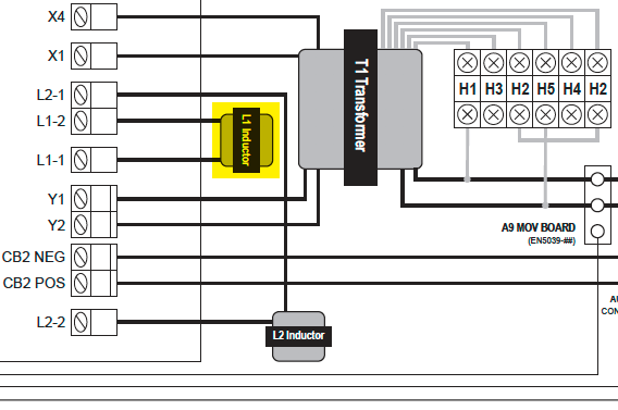
- L1-Main Filter Inductor
- Shown in center of silkscreen. Located on bottom-left of back wall. It is part of the dc filter, lowering ripple.
![]()
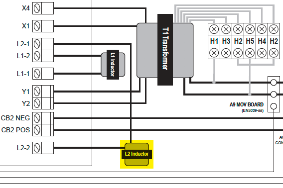
- L2-Secondary Filter Inductor
- Shown bottom-center of silkscreen. Located on bottom of back wall to right of Filter Inductor (L1). It is also part of the dc filter.
![]()
- T1-Power Isolation Transformer
- Shown at center of silkscreen. Located on back wall above the filter inductors (L1/L2). Provides isolation and converts ac input voltage to appropriate potential, prior to rectification.
![]()
p(banner tip). ATevos with the multi-tap ac input option (smart part code ‘MT1/2’), feature a terminal block (TB-H#) mounted above the AC Input Circuit Breaker (CB1) for voltage selection. Jumper positions are shown on silkscreen to right of Power Isolation Transformer (T1). See Section entitled “ATevo with Selectable Input Voltage.”

Last modified:
11 May 2021