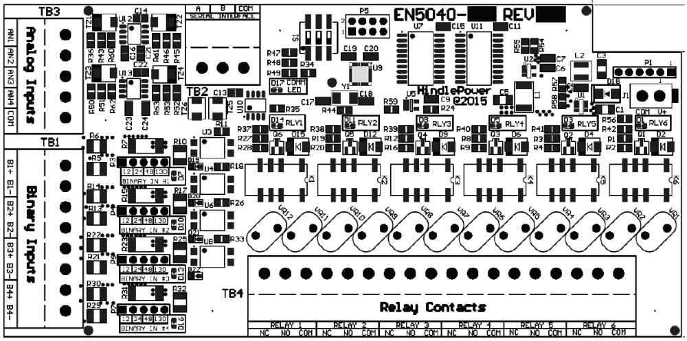
The Auxiliary I/O Board (A4) is an optional component that mounts near the top of the heat sink on the left side of the ATevo . It is equipped with six (6) relays, four (4) generic Binary Inputs, and four (4) generic Analog Inputs.
The Auxiliary I/O Board (A4) communicates to the Main Control Board (A1) via serial communications. The Serial Communications Connection is part of the ribbon cable between the Main Control Board and the Power Board (A2). A green communications LED is located adjacent to the TB2 terminal block of the Auxiliary I/O Board.
This LED will blink to indicate active communication between the Auxiliary I/O Board and the Main Control Board. All relays are failsafe such that if communication is lost between the Main Control Board (A1) and the Auxiliary I/O Board (A4), the relays will switch to the alarm state.
Click on the toggles below for detailed information about the components of the Auxiliary I/O Board:
- Relays
-
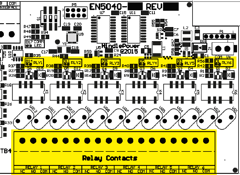
The Auxiliary I/O Board (A4) contains six (6) configurable one (1) form-C relays. Relay contacts are rated for 0.5A @ 125 Vac/Vdc.
Each relay has:
- a red LED that serves as a debugging aid that illuminates when the relay is in alarmed state
- a second contact set which feeds back the relay’s state to ATevo’s main processor
![]()
Each relay is configurable to:
- change states based on any alarm condition or status point
- be latching or non-latching
- switch to active state after a pre-programmed delay
- Binary Inputs
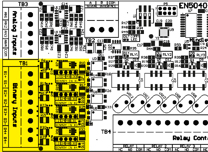
The four (4) Binary Inputs are optically isolated from ATevo and each other. They can be configured via jumper selection to accept input voltages of 12Vdc, 24Vdc, 48Vdc, or 130Vdc. Each Binary Input has an associated yellow LED and a jumper selection block. The LED serves as a debugging aid as it will illuminate when the associated Binary Input is high (in the ‘ON’ state).
The Binary Inputs may be configured to be active high or active low and generate alarms and controls such as charger shutdown. The configuration also permits each input to be assigned a custom name (such as ‘2% Hydrogen’, or ‘Vent Fan Fail’). ATevo will report all activity of the input (status, alarms or log files) by the generic default name or the custom configured name.
![]()
- Analog Inputs
-
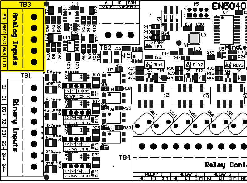
The four (4) Analog Inputs are rated for 0-10 Vdc. They utilize a common ground, referenced to DC OUTPUT NEG, and can be used to import generic analog values. ATevo assigns each Analog Input a unique generic name such as ‘AUX 1 input AN1’. This name can be changed to be readily identifable by the end user (e.g. ‘Ambient Temp’). ATevo will report all status and alarms with the default name or the custom name assigned.
The Analog Inputs include scaling configuration such that ATevo can report their values in primary units. For example, a temperature transducer with a 0 to 10 Vdc output can be configured to scale the voltage value directly to the associated temperature represented by the dc voltage. The associated ‘units’ name can also be configured such that when the Analog Input value is displayed, it will display as ‘80.3 F’ instead of ‘6.2 Vdc’.
Each Analog Input can be configured to generate alarms based on its value. Available trigger conditions to generate an alarm include below a threshold, above a threshold, within a range, or outside a range. Threshold and range values are configurable, and are entered in the primary units (such as °F) based on scaling configuration.
![]()