Overview
The Hindle Health System (HHS) is a powerful, user friendly, standard feature that tests and reports on ATevo’s operational health. Some portions of the HHS continuously run in the background. Other parts require user intervention.
Components
The Hindle Health System is composed of four (4) major components. The details of each are shown by clicking on the toggles below:
- Self-Diagnotics Utility (runs in background)
- ATevo microprocessors continuously run utilities that check hardware component operation including: memory, communications interfaces, parameters, and discrete devices such as relays.
They also test that all input values and measurements are within tolerance of reasonable ranges. Some critical parameters such as dc voltage and dc current are sampled by multiple processors and have redundant qualification requirements. Any errors detected are reported immediately by alarms and/or status updates. The utilities provide possible causes and proposed solutions to resolve issues found. - Hindle Health Button
-
![]() The Hindle Health Button is on the lower-right corner of the control panel overlay. When pressed, it starts the user-assisted portion of the Hindle Health System. This process will check areas of the battery charger that the continuous self-diagnostics cannot. For example, ATevo cannot test a relay’s performance without forcing it to change state. The user will be guided through the test procedure via the Hindle Health Screens described later in this Section.
The Hindle Health Button is on the lower-right corner of the control panel overlay. When pressed, it starts the user-assisted portion of the Hindle Health System. This process will check areas of the battery charger that the continuous self-diagnostics cannot. For example, ATevo cannot test a relay’s performance without forcing it to change state. The user will be guided through the test procedure via the Hindle Health Screens described later in this Section.
- Hindle Health LEDs
- Hindle Health LED Indicators are at the bottom of the front panel overlay.
- GREEN LED, when lit, indicates ATevo is healthy.
- RED LED, when lit, indicates ATevo has an issue. Urgency of action required depends upon if it is:
- Blinking – Immediately replace Main Ctrl Board (A1). There is a critical failure of the microprocessor driving the display and front panel controls. LCD display may be blank, frozen, or displaying corrupted data. Core microprocessor responsible for charging the battery may still be operational.
- Solid – ATevo requires attention, but the condition is not critical. In most cases, LCD display will operate and be able to report the issue and give instructions on how to resolve it. RED LED is illuminated when ATevo detects any error condition, when any alarm is active, or when the Hindle Health System detects any non-normal operating condition.
- Hindle Health Screens
- Hindle Health System screens allow the user to test ATevo to ensure it is operating correctly. Screens permit the user to simulate alarm conditions, check set points and parameters, exercise relays, and verify indicators are working as designed. Step-by-step guidance is provided through the testing process. To start the Hindle Health System, press the Hindle Health Button.
![]()
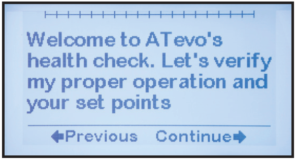
Introduction & Warning Screens
The first few health screens inform the user of how to navigate through the testing process and how to track progress. The next screens warn about any hazardous conditions and identify any tools required. To exit testing at any point, press ESC.
![]()
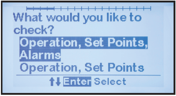
Test Selection
After the initial introduction and safety screens, a screen prompts the user to select the tests to run.
![]()
There are two (2) test selections. The second will not test alarms or
relays:- Operation, Set points, Alarms
- Operation, Set points
Test Screens
The remaining screens are test screens. They prompt the user through an interactive process to verify ATevo’s operation. The process will:
- Require the user to confirm that LED indicators are lit, that relays change state, and that the set points are correct.
- Simulate alarm conditions and prompt the user to verify the alarms operate and are confirmed by any connected SCADA devices.
- Explain how to verify ATevo calibration and automatically enter calibration mode if required.
After the Hindle Health System completes testing, ATevo will return to the Home Screen. An event will be added to the log file along with a time and date stamp. The results of each test are included in the log file. The result status will indicate that each test PASSED, FAILED, or was NOT RUN. The resulting log file can be used to prove NERC compliance requirements for things such as verifying correct float voltage.