
モジュールハードウェア /
I/Oコネクタ
 |
取り外し可能なすべてのコネクタ上のワイヤターミナルは「CAGE CLAMP」式であるため、ワイヤ挿入のためクランプを開ける際には、ワゴ(同等の配線具)、または先の細いドライバーが必要となります。 |  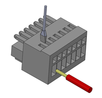 |
| I/Oコネクタプラグ | |
|---|---|
| 部品番号 | Pulseroller Order Code: 1597-0001 (Degson 8EDGK-2.5-07P-11) |
| ワイヤサイズ | 28 – 20 AWG (0.2 – 0.5 mm 2) |
| 条長 | 5 – 6 mm |
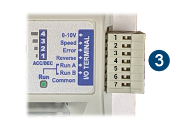
| ピン | 信号 | 指示 | 説明 |
|---|---|---|---|
| 1 | 0-10V | 入力 | 速度制御用の0~10ボルトアナログ入力 |
| 2 | Speed | 出力 | MDRの速度に比例した周波数出力 |
| 3 | Error | 出力 | エラー状態が有効になった場合は、+24Vまたは0Vの出力を提供 |
| 4 | Reverse | 入力 | +24Vまたは0Vの入力を受け入れてDIPスイッチ“CONFIG”-2に設定した反対方向にモーターを駆動 |
| 5 | Run A | 入力 | +24Vまたは0Vの入力を受け入れて速度制御状態で駆動(「Run A」および「Run B」の入力参照) |
| 6 | Run B | 入力 | +24Vまたは0Vの入力を受け入れて速度制御状態で駆動(「Run A」および「Run B」の入力参照) |
| 7 | Common | PNPバージョン | 入力(Run A、Run B、Reverse)のオプトカプラー用の共通DC |
| NPNバージョン | 入力(Run A、Run B、Reverse)のオプトカプラー用の共通+24V |