
DIPスイッチ設定 / 構成DIPスイッチ /
保持ブレーキ設定
保持ブレーキの定義
| 方法 | 説明 |
|---|---|
| 通常 | 標準ダイナミック分巻コイル:EZ-Qube Module モジュールが構成済みの減速機能を実行した後、モジュール内の3個のモーター電力トランジスタ回路のそれぞれが内部でアースに分流されます。ギアボックスの機械的慣性とモーターローターの磁性抵抗によって、保持力が生まれます。 MDR業界標準の保持ブレーキ手法です。 |
| 自由 | 自由スピン:EZ-Qube Module モジュールが構成済みの減速機能を実行した後、モジュール内の3個のモーター電力トランジスタ回路のそれぞれが内部で開となります。ギアボックスの機械的慣性のみによって保持力が生まれます。 |
| サーボブレーキ | アクティブサーボ:EZ-Qube Module モジュールが構成済みの減速機能を実行した後、モーターローターの位置を記憶し、モーターコイルにアクティブ電力を提供してローラー位置を保持します。 |
保持ブレーキ選択DIPスイッチ設定
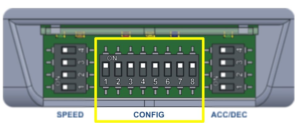
| 通常 | CONFIG SW 7 |
CONFIG SW 8 |
|---|---|---|
| 自由 | OFF | OFF |
| Free | ON | OFF |
| サーボブレーキ | OFF | ON |