English
Japanese
EZ-Qube Reference Manual
2.0
4.1
3.0
3.1
4.0
2.0
Table of Contents
EZ-Qube Reference Manual
2.0
EZ-Qube Reference Manual — 4.1
EZ-Qube Reference Manual — 3.0
EZ-Qube Reference Manual — 3.1
EZ-Qube Reference Manual — 4.0
EZ-Qube Reference Manual — 2.0
1.
About This Manual
2.
Glossary of Terms
3.
Module Hardware
3.1.
Identifying Module Components
3.2.
Mounting Dimensions
3.3.
Power Connector
3.4.
Motor Connector
3.5.
I/O Connector
3.6.
Inspection and Cleaning
3.7.
Technical Specifications
4.
Module Wiring
4.1.
Power Supply
4.2.
Proper Motor Grounding Practice
4.3.
Run/Reverse Inputs
4.4.
0-10V Analog Input
4.5.
PNP Version
4.5.1.
Error Output
4.5.2.
Speed Signal Output
4.6.
NPN Version
4.6.1.
Error Output
4.6.2.
Speed Output
5.
DIP Switch Settings
5.1.
CONFIG DIP Switch
5.1.1.
Holding Brake Settings
5.2.
SPEED DIP Switch
5.2.1.
0-10V Analog Speed
5.2.2.
Speed Calculation
5.3.
ACC/DEC DIP Switch
5.3.1.
Accel/Decel Equal
5.3.2.
Decel Equal 2 x Accel
5.3.3.
Accel/Decel Time Formula
6.
Operation
7.
Output Signals & LED Indicators
7.1.
Pulse Speed Output
7.2.
Error Output and LED Status
7.2.1.
Power Supply ON with Motor Connected
7.2.2.
Motor Not Connected
7.2.3.
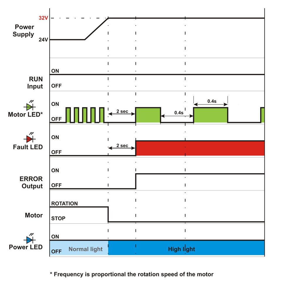
Power Supply Voltage > 32V
7.2.4.
Voltage Drop Below 18V and Voltage Drop Below 13V
7.2.5.
Voltage Over 32V Due to Motor Overspeed
7.2.6.
Normal Operation with Motor Running then Reverse Signal
7.2.7.
Motor Current Exceeding Peak Limit
7.2.8.
Over Current with PWM Limiting
7.2.9.
Motor Stalled with Self Stop
7.2.10.
Motor Overload with Self Stop
7.2.11.
Module Over Heat with Self Stop
7.2.12.
Motor Not Running when RUN is ON
7.2.13.
Motor Phases Error Detected
8.
Internal Jumper Settings
Download as PDF
7.2.3.
Power Supply Voltage > 32V
7.2.2.
Motor Not Connected
7.2.4.
Voltage Drop Below 18V and Voltage Drop Below 13V
7.2.2.
Motor Not Connected
7.2.4.
Voltage Drop Below 18V and Voltage Drop Below 13V