
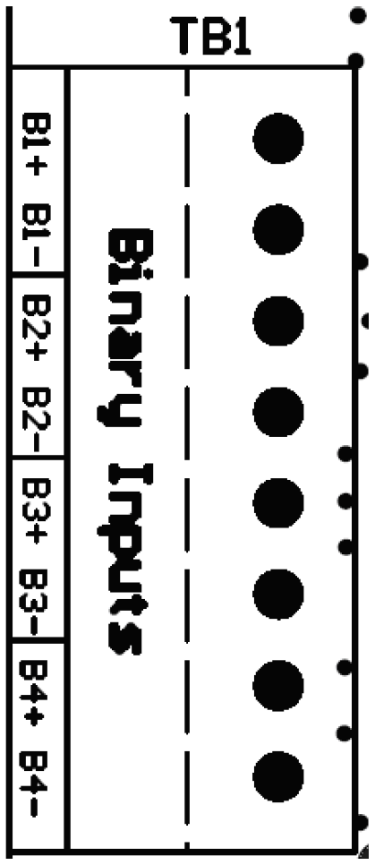
| Connections to Binary Inputs are made through an 8-pos terminal block (A4-TB1). The terminal block is removable to simplify wiring. The terminal connections are labeled along the edge of the Auxiliary I/O Board next to terminal block (A4-TB1). Each Binary Input is optically isolated and has a polarized pair of terminals. Observe the pos(+) and neg(-) designators when wiring the terminal block. |
 |
Procedure
- De-energize and lock out all ac and dc voltages to ATevo.
- Allow internal voltages to dissipate, and check with a voltmeter.
- Remove safety shield.
- Route Binary Input wiring to Auxiliary I/O Board (A4) through an unused enclosure knockout.
- Connect wiring (#22-14 AWG) to appropriate terminals on the Auxiliary I/O Board (A4-TB1).
- Strip each wire 0.25in / 6.4mm, and tighten terminal screws.
- Replace the safety shield.
- Re-energize ATevo.
Notes
- Binary Inputs are configurable for 12Vdc, 24Vdc, 48Vdc, or 130Vdc.
- Terminal block (A4-TB1) is compression type, accepting #22-14 AWG wire.
- Correct polarization is required.
Last modified:
14 September 2022