
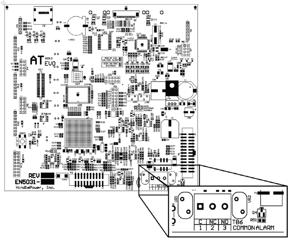
ATevo Main Control Board (A1) is equipped with a ‘summary’ Common Alarm relay. This relay contact transfers when any one (1) or more of the standard ATevo alarm(s) become active. One (1) set of form-C alarm contacts is provided, and are accessible via terminal block (A1-TB6) on the Main Control Board. Refer to figure below.
PROCEDURE
- Allow 30in / 762mm of wire inside enclosure, and trim excess.
- Route annunciator wires to ATevo front panel door by following existing harness past door hinge.
- Use two (2) wire ties and allow a 4-6in / 102-153mm loop for the hinge.
- Trim wires to length to connect to alarm terminal block (A1-TB6), and strip 0.25in / 6.4mm of insulation.
- Make connections at A1-TB6 and tighten compression screws.
NOTES
- Alarm contacts are rated at 0.5A / 125 Vac or Vdc.
- Common Alarm relay terminal block (A1-TB6) is compression type, accepting wire sizes #22-14 AWG.
- Terminals are labeled in the non-alarm condition, with ATevo operating ‘normally’ and relays energized.
- If user alarm contacts (A1-TB6) are to drive inductive dc loads (e.g. a larger dc relay) an external protective diode must be installed at the dc relay to avoid equipment damage. Refer to Application Note (JD5011-00).
Last modified:
3 August 2023