
| Connections to the Analog Inputs are made through 5-pos terminal block (A4-TB3). The terminal block is removable to simplify wiring. Terminal connections are labeled along the edge of the Auxiliary I/O Board next to terminal block (A4-TB3). The Analog Inputs are NOT isolated and must be referenced to the negative(-) dc bus. | 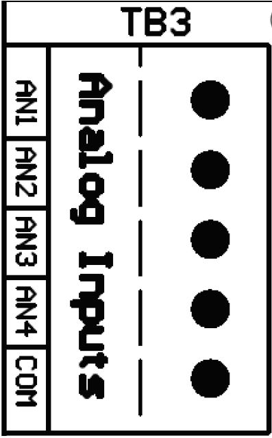 |
Procedure
- De-energize and lock out all ac and dc voltages to ATevo.
- Allow internal voltages to dissipate and verify with a voltmeter.
- Remove safety shield.
- Route remote analog inputs to the Auxiliary I/O Board (A4) through an unused enclosure knockout.
- Connect signal wiring (#22-14 AWG) to appropriate terminals (A4-TB3) of the Auxiliary I/O Board.
- Strip each wire 0.25in / 6.4mm, and tighten terminal screws.
- Replace the safety shield.
- Re-energize ATevo.
Notes
- Analog Inputs are rated at 0-10Vdc.
- Terminal block is compression type and accepts #22-14 AWG.
- All Analog Inputs (AN1, AN2, AN3, AN4) must be referenced to the ATevo negative(-) bus voltage (COM) terminal.
Last modified:
5 May 2021