
Installer is responsible to provide suitable dc output, battery, and dc load wiring.
Guidelines for DC Connections
- Size the dc wiring to minimize voltage drop. Acceptable wire size depends on the installation. As a guideline, voltage drop should not exceed 1% of nominal output voltage at full current. Refer to the following table to determine the voltage drops for various wire sizes, currents and distances.
| Wire Sizing Chart | |||||
|---|---|---|---|---|---|
| Voltage Drop per 100ft / 30.5m of Wire (for copper at 68 F / 20 C) | |||||
| Wire Size (AWG) | DC Current (Amperes) | ||||
| 30 | 40 | 50 | 75 | 100 | |
| 10 | 3.0V | 4.0V | 5.0V | not recommended | not recommended |
| 8 | 1.9V | 2.5V | 3.1V | not recommended | not recommended |
| 6 | 1.2V | 1.6V | 2.0V | 3.0V | not recommended |
| 4 | 0.7V | 1.0V | 1.2V | 1.9V | 2.5V |
| 2 | 0.5V | 0.6V | 0.8V | 1.2V | 1.6V |
| 0 | 0.3V | 0.4V | 0.5V | 0.7V | 1.0V |
Example: 100ft / 30.5m of #8 AWG wire at 50A has a 3.1V drop.
- ATevo is factory wired to regulate output voltage at the output terminals. If total voltage drop is greater than 1% (e.g. 1.3V for a 130 Vdc system), remote sense wiring is recommended (see Section 13, Remote Sense ).
- Do not run external ac and dc power wiring through the same conduit.
- Facility-specific installation requirements take precedence.
Click the toggle below to see the DC Output connections required for your ATevo’s enclosure style:
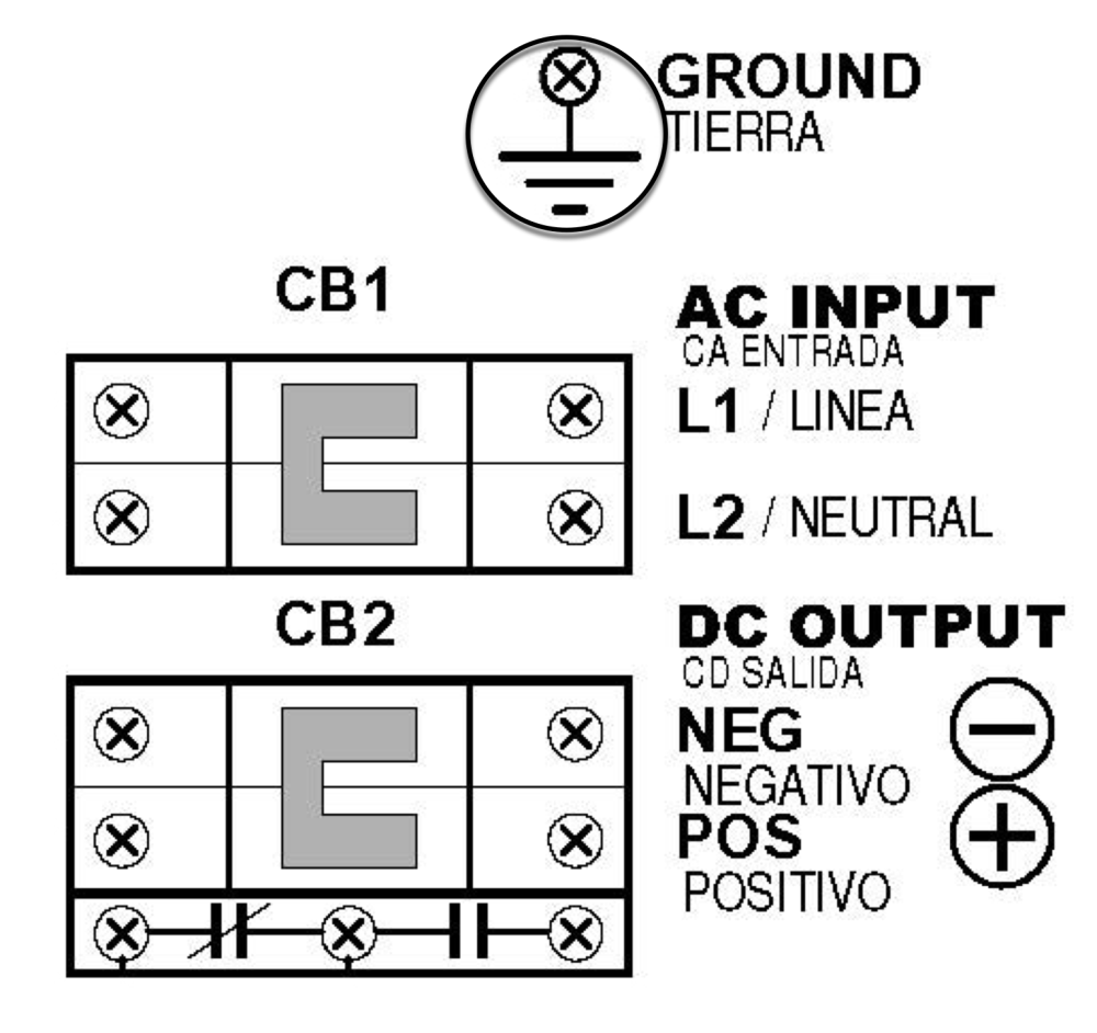
- I/O Connections (Style-5054)
- Use a dc disconnect switch or circuit breaker between ATevo and the dc bus. This device should have lockout capability to allow ATevo to be disconnected from the dc bus for maintenance.
- Remove safety shield per Removing Protective Safety Shield in Section 4.
- Run dc wiring to Output Circuit Breaker (CB2).
- Connect wires to appropriate locations on the DC Output Breaker (CB2+/-) as indicated on drawing above.
- Using a flat-blade screwdriver, securely tighten compression screws on DC Output Breaker Terminals (CB2+/-).
- Reinstall safety shield after you have made and checked all connections.
![]()
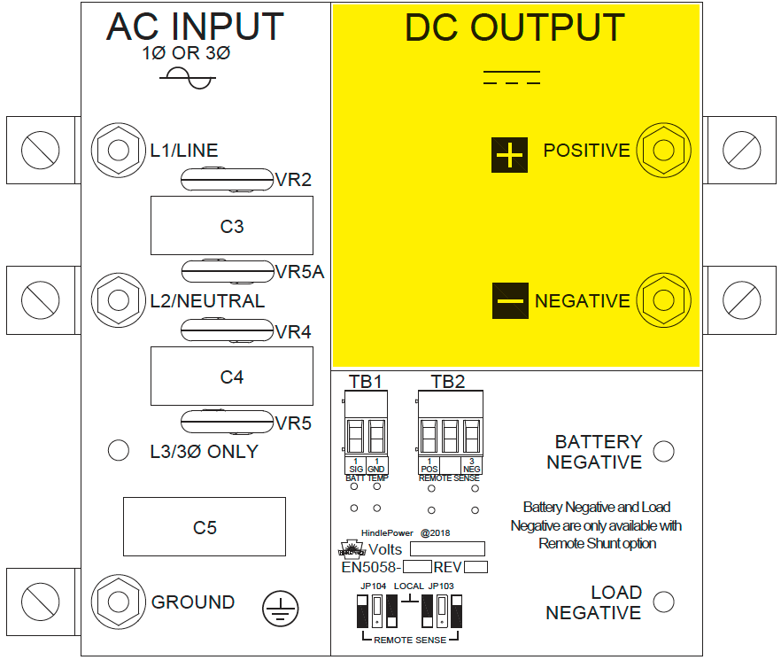
- I/O Connections (Style-5070)
![]()
- Use a dc disconnect switch or circuit breaker between ATevo and the dc bus. This device should have lockout capability to allow ATevo to be disconnected from the dc bus for maintenance.
- Remove safety shield per Removing Protective Safety Shield in Section 4.
- Run dc wiring into ATevo, ending at right side of I/O panel.
- Connect wires to appropriate dc output CU-AL compression lugs on right side of I/O panel.
- Using a flat-blade screwdriver, securely tighten lugs for pos(+) and neg(-) connections.
- Check all dc output connections, and reinstall safety shield.
![]()
Last modified:
11 May 2021