
ATevo must be configured to sense dc output voltage used for regulation at either the charger’s dc output or at the voltage present on the Remote Sense terminal block (A2-TB1). This configuration is accomplished by moving shorting block jumpers located on ATevo’s Power Board (A2).
Locating Remote Sense Configuration Jumpers
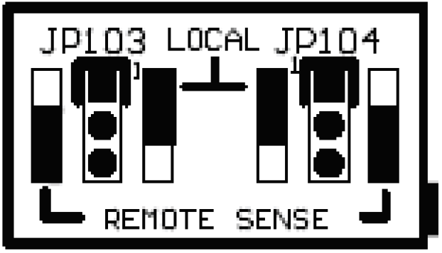
Remote Sense Configuration Jumpers (JP103 and JP104) are located on the Power Board next to the Remote Sense terminal block (A2- TB1). Each jumper consists of a 3-pin header and a SHORTING BLOCK that shorts (or connects) two (2) pins of the header together.
Enabling Remote Sense
To have ATevo regulate dc output to the voltage present at the Remote Sense leads, move both the Remote Sense SHORTING BLOCKs (JP103 and JP104) to the REMOTE SENSE side of the pin headers. The SHORTING BLOCKS should be installed on the two (2) pins closest to the edge of the board.
Enabling Local Sense
Local Sense is the factory default configuration. Unless otherwise specified, all ATevos are shipped configured to use local sense. In this configuration, ATevo regulates dc output to the voltage present at the charger output terminals (CB2+/-).
Jumper configuration will have both Remote Sense SHORTING BLOCKs (JP103 and JP104) at the LOCAL SENSE side of the pin headers. SHORTING BLOCKS will be installed on the two (2) pins farthest from the edge of the board.