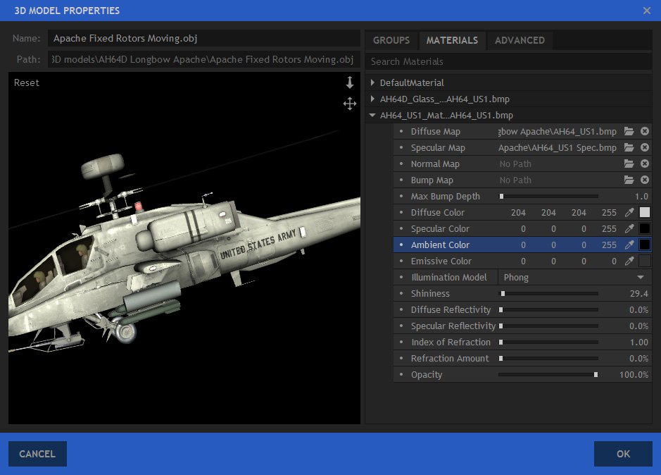
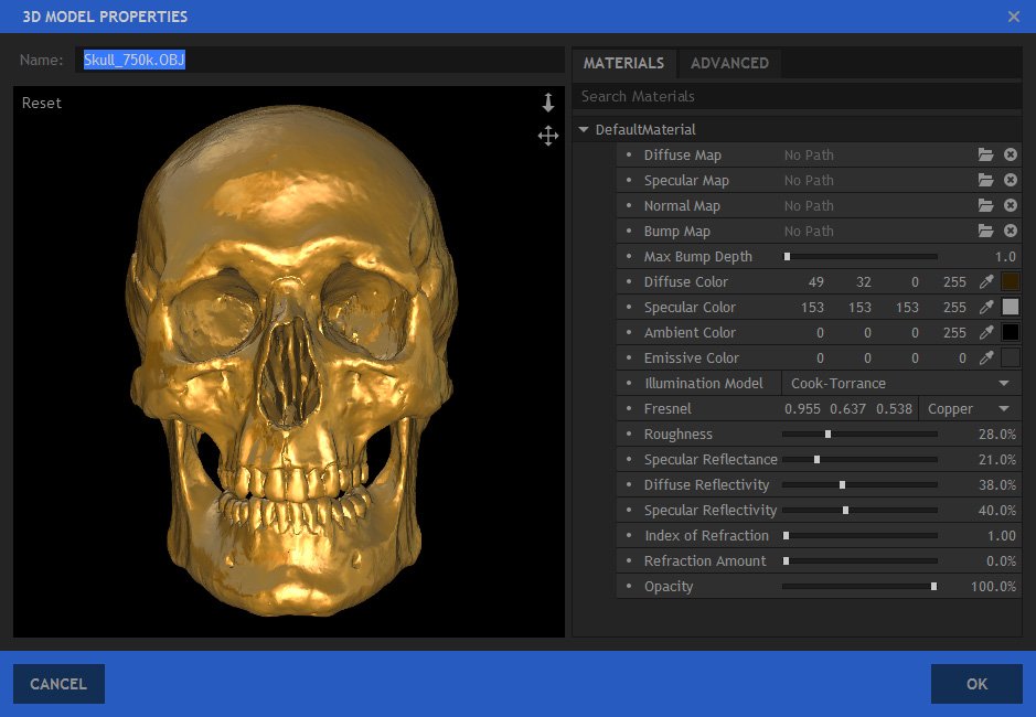
A model’s textures are listed in the Materials panel. This is displayed during import and can be accessed again at any time after import byfinding the 3D model in the Media panel, and clicking the cog icon next to it, or choosing Properties from its menu.
The appearance of a 3D model in your scene can be drastically altered using the materials options. For realistic results we recommend setting up each material.
Models will often have multiple materials, representing different parts of the model. The glass in a car’s windows will be a separate material to the metal on the doors, for example.
Selecting a material in the list will highlight it with a red mesh in the preview, so that you can see precisely which part of the model you are adjusting.
Texture Maps
At the top of a material’s options are four texture map slots. These are used to add detail and color to the 3D geometry.
Compare the difference between an untextured model:
And the same model with textures and materials set up:
Most 3D models have been designed with textures. HitFilm will attempt to import textures automatically during import, if they are located in the same folder as the 3D file.
If textures are not found automatically or if you want to change a texture, you can locate a new one using the folder icon. You can remove a texture from a slot using the X button.
Diffuse Map
The diffuse map is used to add surface detail and color to the model. Here is an example of a helicopter, with the diffuse map providing dirt detail on the hull as well as lettering:
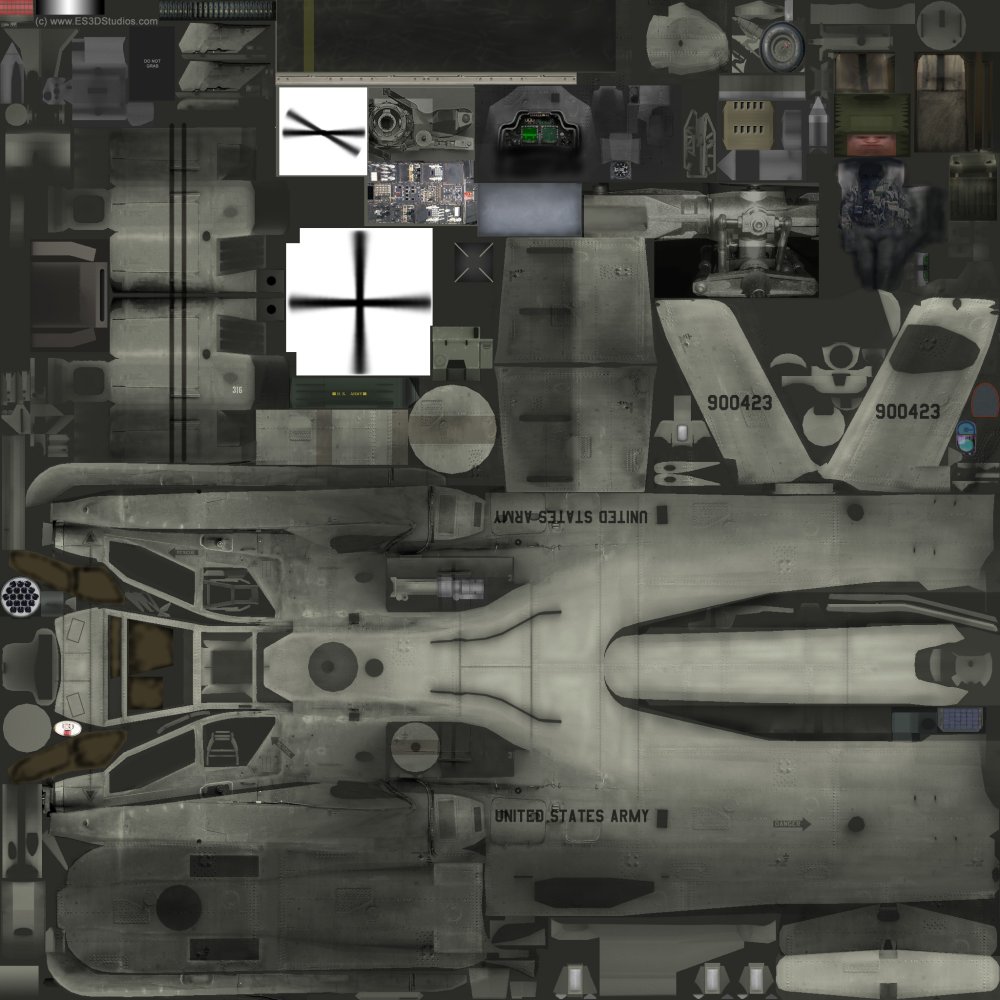
The image file for the diffuse map looks like this:
Textures are not made inside HitFilm. Instead, they are produced when the 3D model is designed and created. However, you can customize textures using any normal image editor, and changes made can be then re-applied in HitFilm.
Specular Map
Specular highlights are created by your lighting setup. By default all surfaces on the model are equally likely to receive specular highlights. Sometimes, however, you may want to restrict specularity based on the material – for example, if you have a normally shiny surface (such as polished metal) covered in dirt and scratches, you will want to restrict the specularity only to the clean areas. This can be achieved using a specular map.
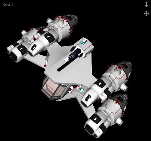
Observe the helicopter, without a specular map:
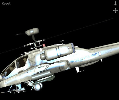
In the above example the specular highlight has been made blue and more extreme, so as to illustrate the point. Ordinarily you would opt for a subtler appearance. Note how the specular highlight is bright along the entire length of the helicopter, including over the UNITED STATES ARMY text.
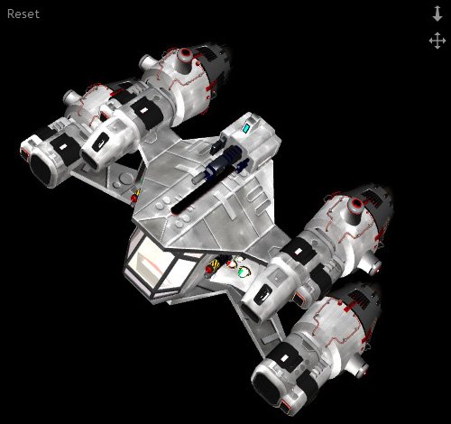
Here is the same model with a specular map added:
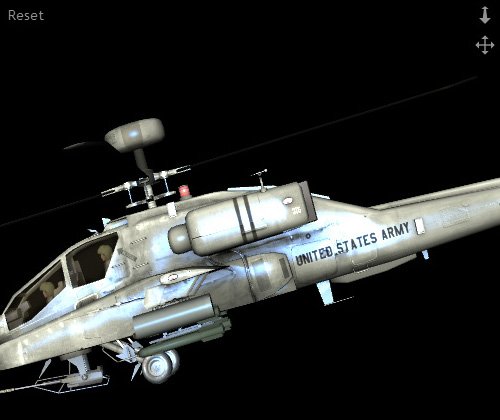
This time, note how the specularity has been restricted. Dirtier areas of the helicopter are less reflective. The UNITED STATES ARMY text is now visible and is not creating highlights – as if the black paint of the text is preventing it. Using a specular map can drastically improve the realism of your 3D models.
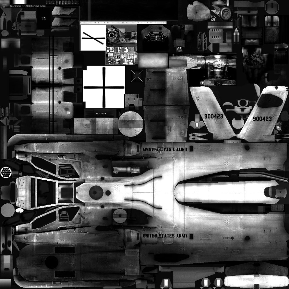
3D models are usually provided with a specular map, but they can also be created by hand. They are greyscale images, with black areas representing non-specular areas and white areas representing high specularity. The specular map for this helicopter is very simple:
The specular map slot also restricts the behavior of the reflectivity options, detailed below.
Normal Maps & Bump Maps
Normal Maps are hugely powerful textures which can be used to add the appearance of additional 3D detail to a model, without actually increasing its polycount. Normal maps are used to create detailed models without negatively impacting performance.
Take this example of a smooth 3D sphere:
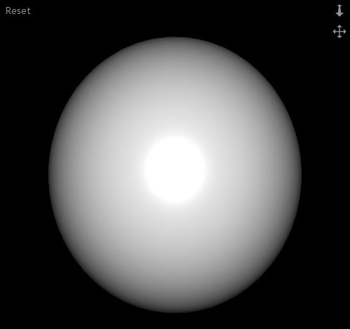
This sphere has no surface detail at all. By applying a normal map this result is achieved:
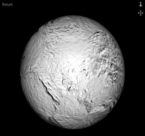
The sphere model now appears to have substantial surface detail. However, it is still the same smooth sphere. The illusion of surface detail is being created entirely by the normal map. The huge benefit is that the model is still very simple, which keeps rendering times low.
There are restrictions to how normal maps function. If you move your camera very close it will become apparent that the detail is texture-based. Similarly, viewing the model from an oblique angle can reveal that the surface detail is only an illusion. And while the normal mapped surface reacts to the position of 3D lights for illumination and shading, normal maps won’t cast actual 3D shadows. Normal maps are therefore best used for subtle, fine surface detail, while major features are represented by actual geometry.
Bump Maps perform a similar task to normal maps but using a different, less sophisticated technique. Bump maps can be created by hand much like a specular map, as they are greyscale images with white representing maximum height and black representing minimum height. Normal maps have to be generated from by 3D modelling software and the textures include information for X, Y and Z vectors.
A common workflow would be to produce a high poly model first, then generate a normal map which can be applied to a low poly version. This retains the illusion of fine detail while keeping fast performance.
Because bump maps are inherently relative, with no actual defined height, you can adjust the scale of bump mapping using the Max Bump Depth property. This does not affect normal maps.
Lighting Colors
The various color properties are used to set up the default colors for the material. These combine with the texture maps and your lighting setup.
- Diffuse color alters the base color of the material under a point, spot or direction light. The luminance of this color determines the brightness of the diffuse texture map.
- Specular color determines the color used for the material’s specular highlights. Specular highlights are only visible if there is a 3D light source in the scene.
- *Ambient*Color defines the color of the material under an ambient light source.
- *Emissive*Color is the color of the material regardless of the lighting setup. Even when the model is unlit or shadowed, it will still emit this color. This is useful for simulating light sources, such as neon objects or lights on a vehicle.
Illumination Model
There are two illumination models available for materials: Phong and Cook-Torrance. In general, Phong is more suitable for plastics with a single specular highlight, while Cook-Torrance is more suitable for metals with a rougher surface that distributes the light less evenly.
Phong
Phong generates a defined highlight similar to plastic materials. Light bounces off the surface evenly. This model has less control than Cook-Torrance.
The color of the highlight is determined by the specular color.
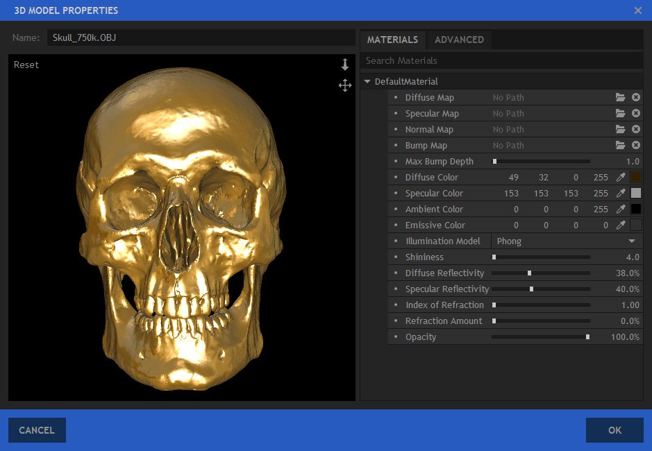
A small Shininess will generate a large highlight, as seen here:
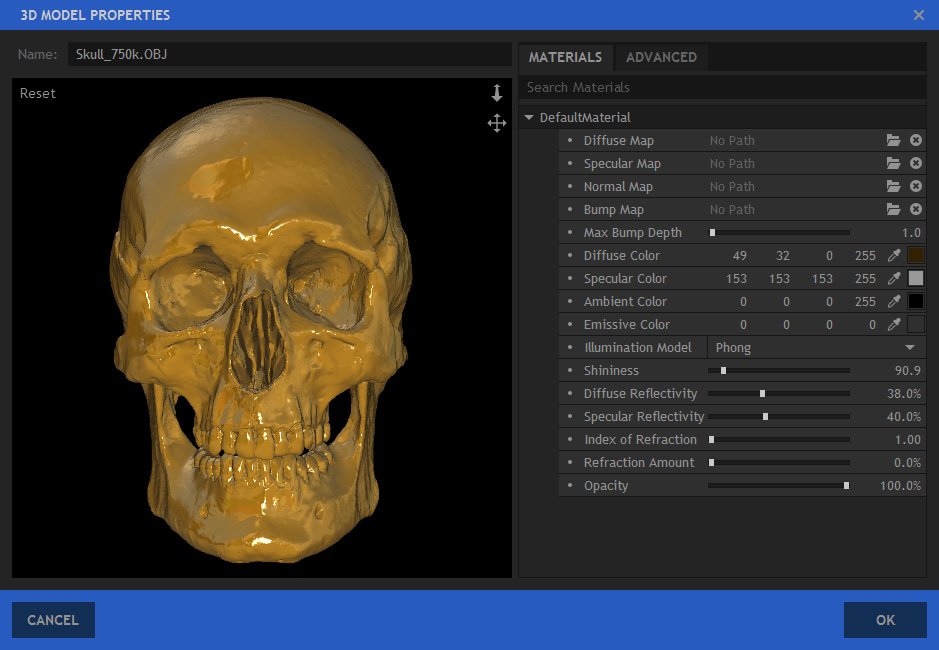
A larger shininess value will generate a smaller, sharper highlight:
Cook-Torrance
This illumination model provides greater control and is more suitable for metal surfaces. Bounced light is scattered across the surface, as if reflecting off multiple ‘microfacets’, rather than a focused, singular bounce as with Phong.
The Fresnel determines the scattering of light. Several metal presets are provided to make it easier to choose a suitable material.
Roughness determines the spread of the specular highlight. A low roughness creates a defined, sharp highlight, while a high roughness diffuses the specular highlight across the surface, moving towards a more matte material.
Specular Reflectance adjusts the intensity of the specular highlight.
In this example a copper fresnel is being used to generate a more realistic metallic appearance, compared to the Phong images above:
Here is the same setup in a more natural lighting scenario:
Reflectivity
There are two types of reflectivity. Specular reflectivity is what we normally think of when we talk about reflections – seeing a visible reflection of an object in the surface of another. Diffuse reflectivity doesn’t produce a direct reflection but causes the object to be illuminated by surrounding objects.
Here is an example image with a single light source and no reflectivity:
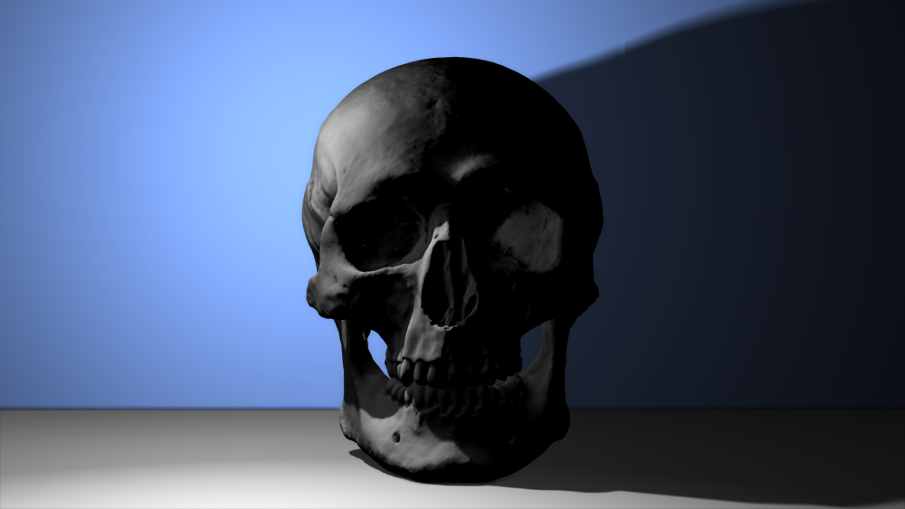
The overall lighting in the above image is unconvincing, because the skull is not being illuminated by it surroundings. While the blue wall and grey floor are not directly emitting light, they should nevertheless be bouncing light.
Here is the same shot with diffuse reflectivity turned on, and no other changes:
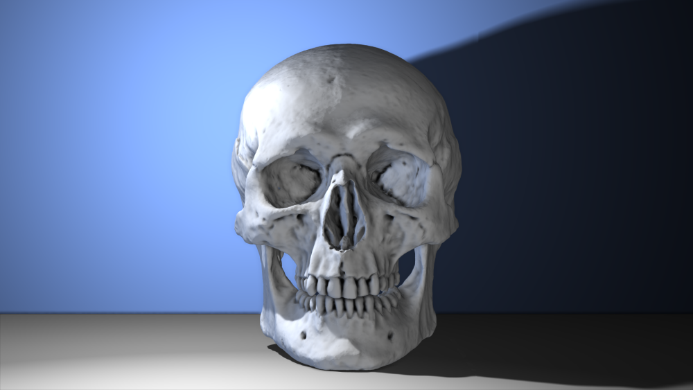
This time the skull sits far more naturally in the scene. It is brighter and is receiving diffuse blue light from the back wall. This still only uses a single light source, but the overall lighting impression is far more realistic. The diffuse reflectivity technique is subtle and hugely powerful – for very little effort you can achieve much more convincing lighting.
Here is the same scene using specular reflectivity instead of diffuse:
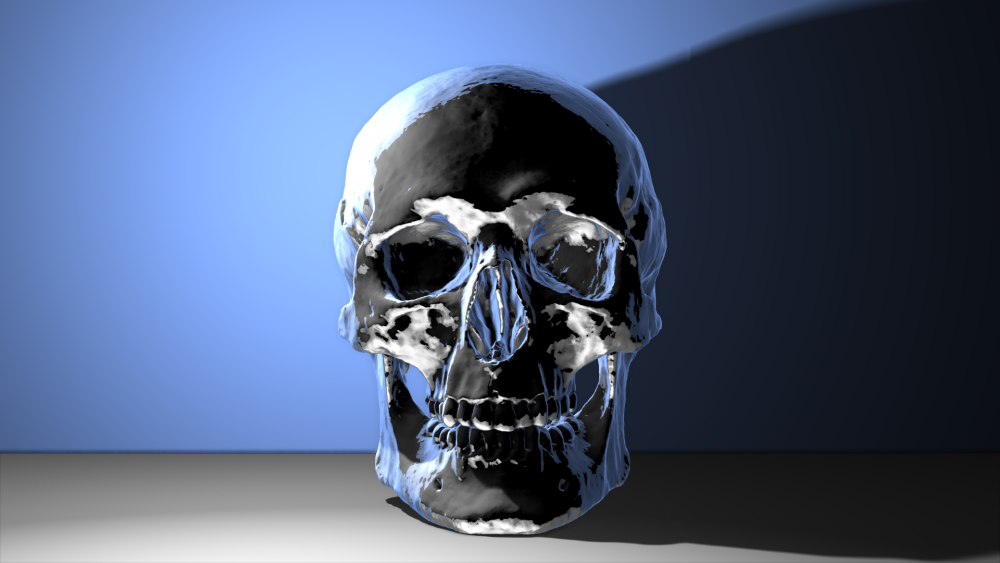
The result is very different. The reflections are very sharp and defined, as if the skull were a shiny chrome material.
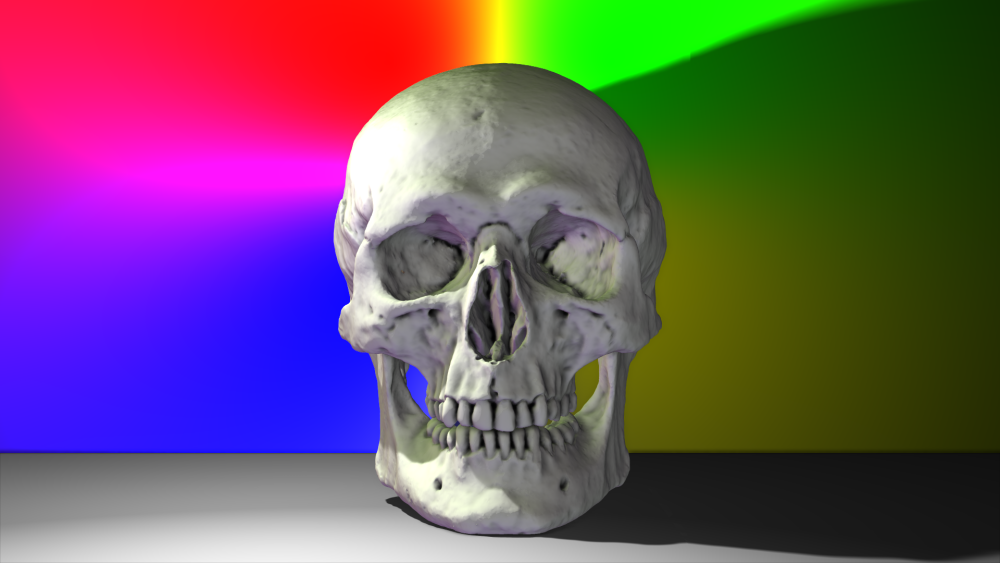
Here is a more extreme example, using the same settings but a different background wall:
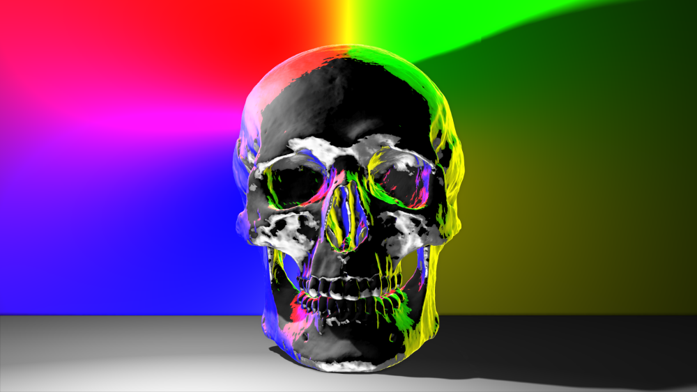
And the same background again, but with a diffuse reflectivity setup:
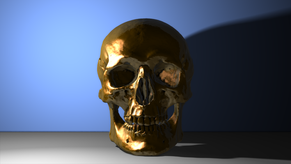
You can, of course, combine the two, which is what you will normally want. That’s how the copper skull was created, using a mixture of diffuse and specular reflectivity:
The amount of diffuse and specular reflectivity can be adjusted per material.
You can also use an environment map image for reflectivity, in addition to the actual 3D scene. An environment map is usually a panoramic, wrap-around image representing a particular location. While this is not as accurate as reflecting the actual 3D scene, it is often more convenient. For example, if you are compositing an object into a live action plate, you are more likely to have a panoramic image of the location than a full 3D recreation.
A 3D layer can be assigned a single environment map. This is set in the material properties of the layer on the timeline. See 3D Objects on the Timeline for more information.
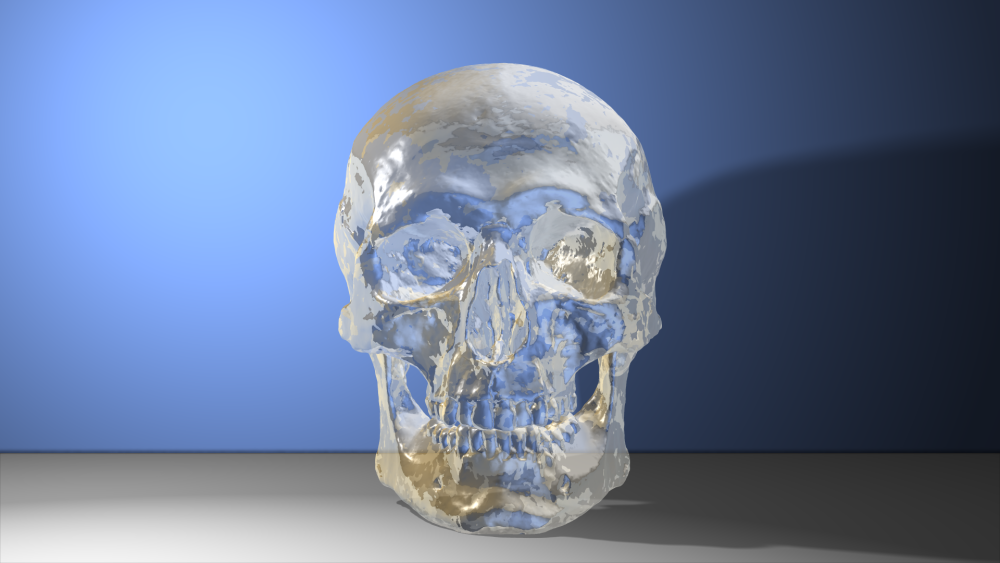
Refraction
Refraction occurs when light is deflected while passing through a semi-transprent object. In HitFilm refraction causes a vertically inverted version of the scene to be visible on the surface of the material.
As with reflectivity, refraction can also use the 3D model layer’s environment map. See 3D Objects on the Timeline for more information.
The Index of Refraction sets the amount of refraction, which differs depending on the density of the material the light is passing through. Water has a refraction index of 1.7 while glass typically starts about 1.55, for example.
The Refraction Amount determines the visibility of the refraction.
Here is an example of the skull object set up to look more like crystal: