Power Connection
Power connector is Degson DG245-5.0, 12 AWG (3.31 mm 2) Max wire size, 5-6 mm strip length
Electrical and Environmental Ratings
| Power supply voltage | 24.0V +/- 10% |
| Input Protection Rating | Class III |
| Standby current consumption | < 120mA |
| Minimum Operating Voltage | 21 |
| Maximum Operating Voltage | 30V |
| Storage temperature | -25ºC to 70º C ( -13ºF to 160ºF) |
| Ambient Operating temperature | Standard Module: 0ºC to 40ºC ( 32°F to 104°F) Freezer Rated Module: -30ºC to 40ºC ( -22°F to 104°F) |
| Humidity | 5% to 95% non-condensing |
| Vibration | 0.152 mm (0.006 in.) displacement, 1G peak |
| Mechanical Shock | 20G peak for 10ms duration (1.0 ms) |
| Enclosure IP Rating | IP54 |
| Motor Starting Current | ≤ 8A per Motor |
| Motor Rated Current | ≤ 3A per Motor |
| Maximum peak current | 21.5A* |
*This is the maximum current that will be allowed by the hardware over current protection circuitry. On board firmware limits the amount of current based on the quantity and motor types connected
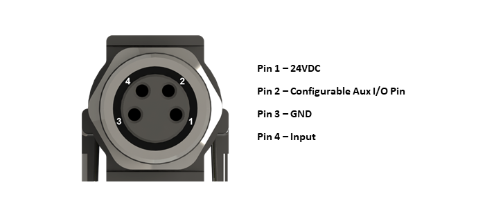
Sensor Port I/O
Each MotionLinx-Ai module is equipped with two 4-pin female M8 style Sensor I/O ports primarily used to connect a photo-electric sensor to the module. Each of these ports has one pin dedicated as an input for the sensor (Pin 4) and one Aux I/O pin (Ppin 2) that is configurable to be either an input or an output.
Input Signals
For the MotionLinx-Ai module, this applies to each Sensor Port’s Pin 4 signal and to the Pin 2 signal when configured as an Input. Pins configured as Inputs are by default auto-sensing for PNP or NPN circuit type such that both sourcing and sinking current will activate the input based upon the following conditions:
| Minimum ON Current | 1.5 mA |
| Maximum OFF Current | 0.4 mA |
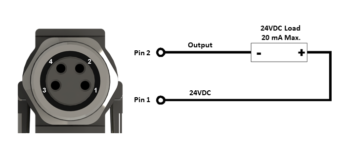
Output Signals Aux I/O Signal (Pin 2) when configured as an OUTPUT
For the MotionLinx-Ai module, this applies to each Sensor Port’s Pin 2 signal when configured as an Output. Pin 2 only provides an NPN circuit as illustrated below.
Sensor Port 24VDC (Pin 1) and GND (Pin 3)
Pin 1 of each Sensor Port provides 24V for powering up an input device (such as a sensor) and/or for supplying the load when Pin 2 is configured as an output. The available current for the two control ports on the module is limited internally by a solid-state fuse. The maximum combined current consumption for the two sensor ports is 100 mA.
Motor Port
| Supported motor types | Senergy Ai |
| PWM frequency* | 25 kHz +/- 0.1% |
| Maximum starting current | 8A |
| Maximum rated current | 3A |
| Motor Protection** | Coil-to-coil short, coil-to-Vcc short, overheating, over-voltage, under-voltage, stall sensing and protection |
- The PWM frequency is firmware version dependent
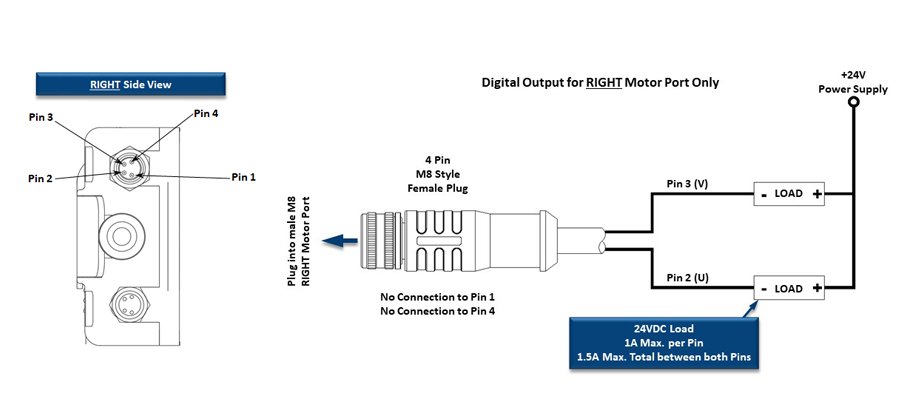
Motor Ports in Digital Output Mode
Either the Left or Right (or both) Motor Ports can be configured to operate their respective motor coil output transistors as 24V DC digital output signals. These digital output signals are sinking type only and will accommodate up to 1A on a given output pin, but restricted to a total of 1.5A for both pins on a given port.
For each of the Motor Ports, only 2 out of the 3 total motor coil output pins are available as digital outputs for a total of 4 Motor Port digital outputs available per module. Please note that these 2 available motor coil pins are different between the Left and Right Motor Ports as illustrated: