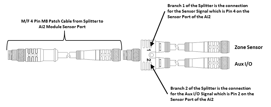
When connecting to either Sensor port with an M8 connector to access Pin 2 signal; you typically will use a standard parallel type splitter cable assembly that breaks out each of the available pins on the Module to their own M8 connection port. These splitter cables wire the +24V and Common connections in parallel
*Splitter cables are commercially available from multiple sources. Click here for information for Pulseroller IOX-2 Breakout/Splitter Module
Typical Parallel Splitter Cable Usage
Aux I/O Pin 2 as Input
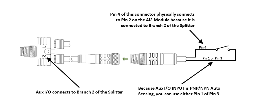
When the Aux I/O Pin 2 is configured as an input, the circuit is NPN/PNP auto-sensing. The signal can be connected to either +24V or 0V to operate.
Aux I/O Pin 2 Input Connection Diagram
!Because the auto-sensing circuit requires a nominal voltage in order to operate, there will be some small amount of leakage current possible between Module Pin 2 and Pin 3 (GND). Please use caution if you connect a load between Module Pin 2 and Pin 3.
Aux I/O Pin 2 as Output
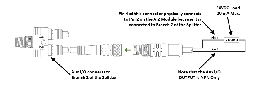
When the Aux I/O Pin 2 is configured as an output, the circuit is NPN only and requires the load to be connected to Pin 1 (+24V)
Aux I/O Pin 2 Output Connection Diagram
!Please note that MotionLinx-Ai Pins configured as outputs are NPN (sinking) which is UNLIKE MotionLinx-IO outputs which are PNP (sourcing)


