These switches are used to select the acceleration and deceleration G force the control uses when starting and stopping the motor respectively. The EQUBE Module acceleration/deceleration control is designed to provide a constant G force or ramp slope regardless of the speed setting for a given SPEED DIP switch setting.
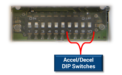
The following chart shows the 16 possible ACC/DEC DIP switch settings for G force ramp and the expected ramp time to reach full speed (when accelerating) or to stop (when decelerating) when the motor speed is set to maximum (Switch setting item 32 from the Speed DIP Switch chart).
| Accel/Decel Times when SPEED setting is 100% maximum | ||||
|---|---|---|---|---|
| SW 7 | SW 8 | SW 9 | SW 10 | Accel/Decel Time (sec) |
| OFF | OFF | OFF | OFF | 0.050 |
| OFF | OFF | OFF | ON | 0.100 |
| OFF | OFF | ON | OFF | 0.200 |
| OFF | OFF | ON | ON | 0.300 |
| OFF | ON | OFF | OFF | 0.400 |
| OFF | ON | OFF | ON | 0.500 |
| OFF | ON | ON | OFF | 0.600 |
| OFF | ON | ON | ON | 0.700 |
| ON | OFF | OFF | OFF | 0.800 |
| ON | OFF | OFF | ON | 1.000 |
| ON | OFF | ON | OFF | 1.200 |
| ON | OFF | ON | ON | 1.400 |
| ON | ON | OFF | OFF | 1.600 |
| ON | ON | OFF | ON | 1.800 |
| ON | ON | ON | OFF | 2.000 |
| ON | ON | ON | ON | 2.500 |
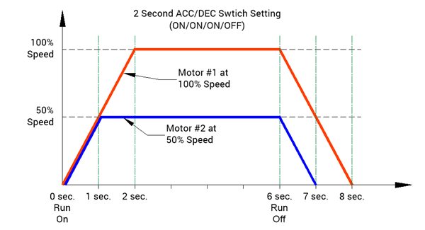
Example with Graph
We have 2 motors, Motor #1 speed is set to 100% maximum RPM and Motor #2 speed is set to 50% speed. If we set the ACC/DEC DIP Switches 4 thru 1 to ON, ON ,ON, OFF we can see from the chart that we should have a 2.000 second acceleration time and a 2.00 deceleration time when our speed is set to 100% maximum. Because the Accel/Decel ramps are the same, if our speed is at 50% of maximum, then our acceleration and deceleration times would be 1/2 of maximum, thus 1.000 seconds for each. In our example, we start both motors at the same time and let them run for 6 seconds and then stop both at the same time. This is shown in the following graph: