
This section provides specifics for implementing Modbus protocol via the ATevo Communications Adapters. The Modbus protocol was implemented using the Modicon Modbus Protocol Reference Guide PI-MBUS-300 Rev. J.
Supported Function Codes
The following standard Modbus function codes are supported:
- 01 – Read Coil Status
- 02 – Read Input Status
- 03 – Read Holding Registers
- 04 – Read Input Registers
- 05 – Read Single Coil
- 06 – Preset Single Register
- 15 – Force Multiple Coils
- 16 – Preset Multiple Registers
The following toggles contain tables that identify all the individual registers provided by this implementation of Modbus.
CLICK ON EACH TOGGLE (+) to open and see table.
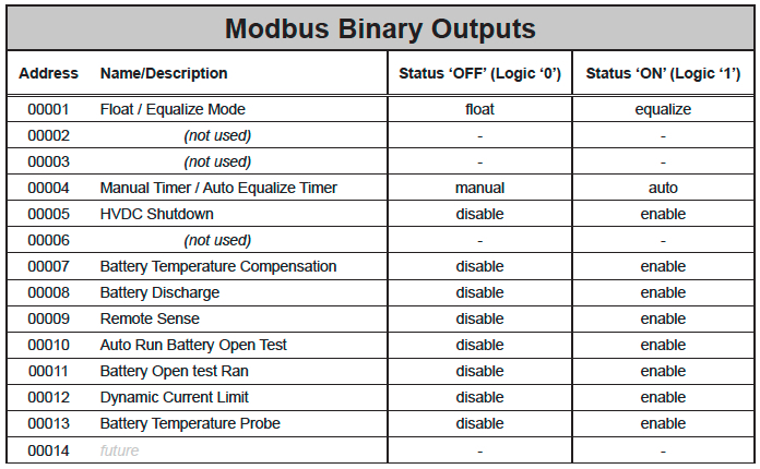
- Modbus Binary Outputs (Coils)
-
![]()
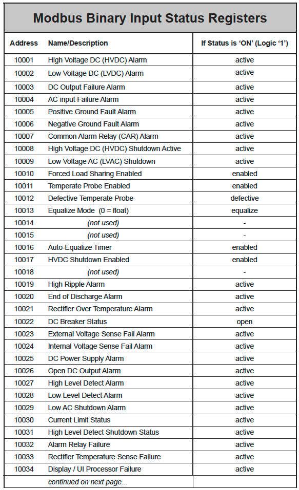
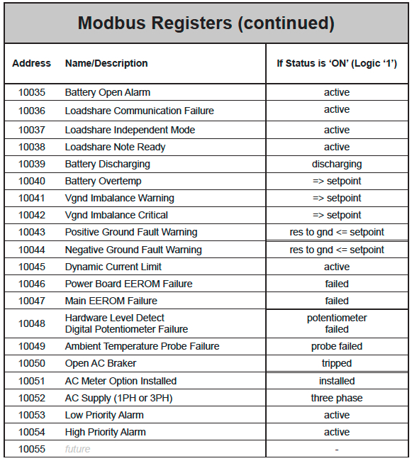
- Modbus Binary Inputs
-
![]()
![]()
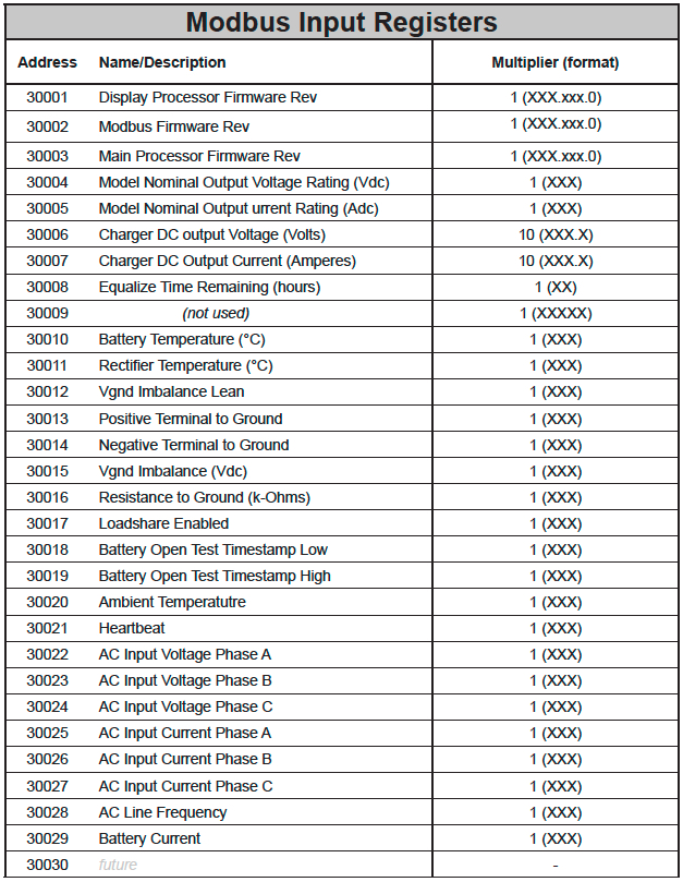
- Modbus Input Registers
- The following table lists the Modbus Input Registers.
![]() For each point, the “Multiplier” column indicates the value by which the register data are multiplied. Since all data are sent in integer format, floating point numbers are multiplied by a constant (1, 10, or 100) to maintain decimal information. For example, registers with two decimal places of resolution are multiplied by 100 (5.67 is sent as 567) while registers with one decimal place of resolution are multiplied by 10 (8.2 is sent as 82). To convert a register to the correct value, simply divide the register value by the “Multiplier” value.
For each point, the “Multiplier” column indicates the value by which the register data are multiplied. Since all data are sent in integer format, floating point numbers are multiplied by a constant (1, 10, or 100) to maintain decimal information. For example, registers with two decimal places of resolution are multiplied by 100 (5.67 is sent as 567) while registers with one decimal place of resolution are multiplied by 10 (8.2 is sent as 82). To convert a register to the correct value, simply divide the register value by the “Multiplier” value. ![]()
![]()
- Upper 8 bits of register value are the Major Version
- Lower 8 bits of register value are the Minor Version
- Example: Version 10.6.0 would be 0×0A06 (hex) = 2566 (decimal)
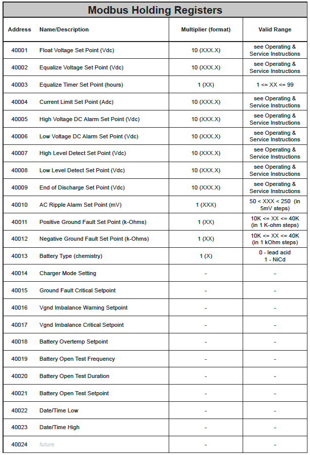
- Modbus Holding Registers
- The following table lists the Modbus Holding Registers.
![]() For each point, the “Multiplier” column indicates the value by which the register data are multiplied. Since all data are sent in integer format, floating point numbers are multiplied by a constant (1, 10, or 100) to maintain decimal information. For example, registers with two decimal places of resolution are multiplied by 100 (5.67 is sent as 567) while registers with one decimal place of resolution are multiplied by 10 (8.2 is sent as 82). To convert a register to the correct value, simply divide the register value by the “Multiplier” value.
For each point, the “Multiplier” column indicates the value by which the register data are multiplied. Since all data are sent in integer format, floating point numbers are multiplied by a constant (1, 10, or 100) to maintain decimal information. For example, registers with two decimal places of resolution are multiplied by 100 (5.67 is sent as 567) while registers with one decimal place of resolution are multiplied by 10 (8.2 is sent as 82). To convert a register to the correct value, simply divide the register value by the “Multiplier” value. ![]()
When writing a value to a Holding Register, you must multiply the desired value by the constant in the “Multiplier’. For example, to change the “Float Voltage Set Point’ to 132 volts, you would need to write 1320 to Holding Register “40001’ (132 × 10 = 1320). The “10’ is the multiplier constant listed in “Multiplier’ column for Holding Register “40001’.![]()
The “Valid Range’ column lists the possible values that can be successfully written to the associated Holding Register. This is the true value and does not include the multiplier correction. Attempting to write values outside of this range will result in a Modbus error returned as an Exception Response.!![]()
![]()
Last modified:
8 August 2022