RS-485 is a standard, defining electrical characteristics of drivers and receivers for use in balanced digital multipoint systems. RS-485 networks can be used effectively over long distances in electrically noisy industrial environments. Multiple devices may be connected to the same network.
Some RS-485 networks may require termination resistors at both ends of the serial network. The decision of whether or not to use termination resistors should be based on the BAUD rate, the cable distance, and the type of cable being used to build the network. In most cases for BAUD rates less than 19.2K, termination resistors are not required. If termination resistors are used, the network must be designed with the appropriate biasing resistors to ensure reliable communications.
Biasing resistors ensure that the network remains in idle state when all drivers are tri– stated. To guarantee that the receivers remain in a known state, +/– 200mV must be maintained across the RS\ 485 inputs, (A) or (–) and (B) or (+). When termination resistors are used, this requires a significantly lower value of biasing resistors which results in greater dc loading of the network. Network design and biasing resistor calculations depend on the number of network nodes, the type of drivers and receivers on the network, and any biasing already designed into other devices sharing the network. As a result, termination resistor decisions, and biasing resistor calculations are beyond the scope of this manual. For more information on biasing and termination details see the following references:
- EIA/TIA-485 Standard Telecommunication Industry Association
- RS-422/RS-485 Application Note Copyright: B&B Electronics
The Serial Communications Adapter board features configurable 120 Ohm termination resistors. Jumpers P4 and P5 enable or disable the terminating resistors.
CLICK ON TOGGLES (+) below to learn more about each type of RS-485 connection:
- 2-Wire RS-485 Connections
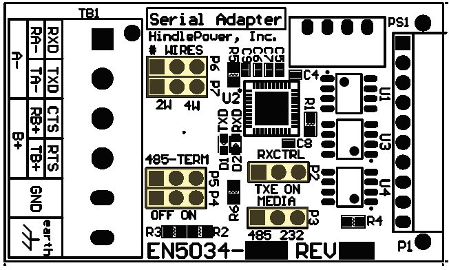
- To make connections and configure settings for 2-Wire connections between the Serial Adapter and an RS-485 network, use the following diagram and tables:
![]()
![]()
![]()
2-Wire RS-485 Settings Jumper(s) Label Setting P3 MEDIA 485 P6, P7 #WIRES 2W P2 RXCTRL TXE P4, P5 485-TERM OFF Wiring Serial Adapter to RS-485 Network Adapter to RS-485 A- (TB1-1) to A- B+ (TB1-3) to B+ GND (TB1-5) to COM - 4-Wire RS-485 Connections
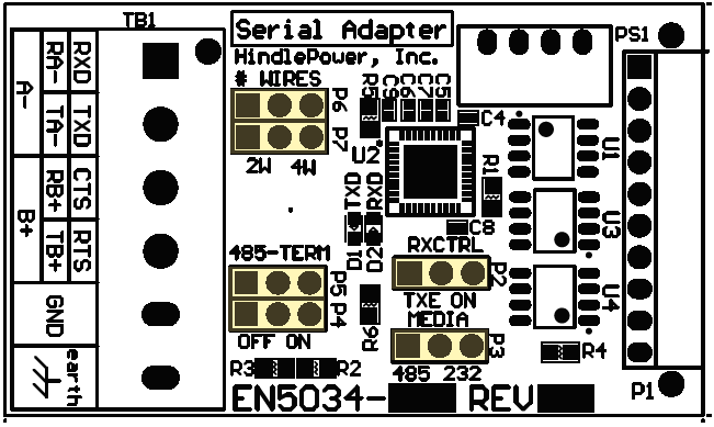
- To make connections and configure settings for 4-Wire connections between the Serial Adapter and an RS-485 network, use the following diagram and tables:
![]()
![]()
![]()
4-Wire RS-485 Settings Jumper(s) Label Setting P3 MEDIA 485 P6, P7 #WIRES 4W P2 RXCTRL ON P4, P5 485-TERM OFF Wiring Serial Adapter to RS-485 Network Adapter to RS-232 RA- (TB1-1) to TA- TA- (TB1-2) to RA- RB+ (TB1-3) to TB+ TB+ (TB1-4) to RB+ GND (TB1-5) to COM