
The tables found within each of the toggles below identify all the individual data points provided by this implementation of DNP3.
CLICK ON EACH TOGGLE (+) to open and see table.
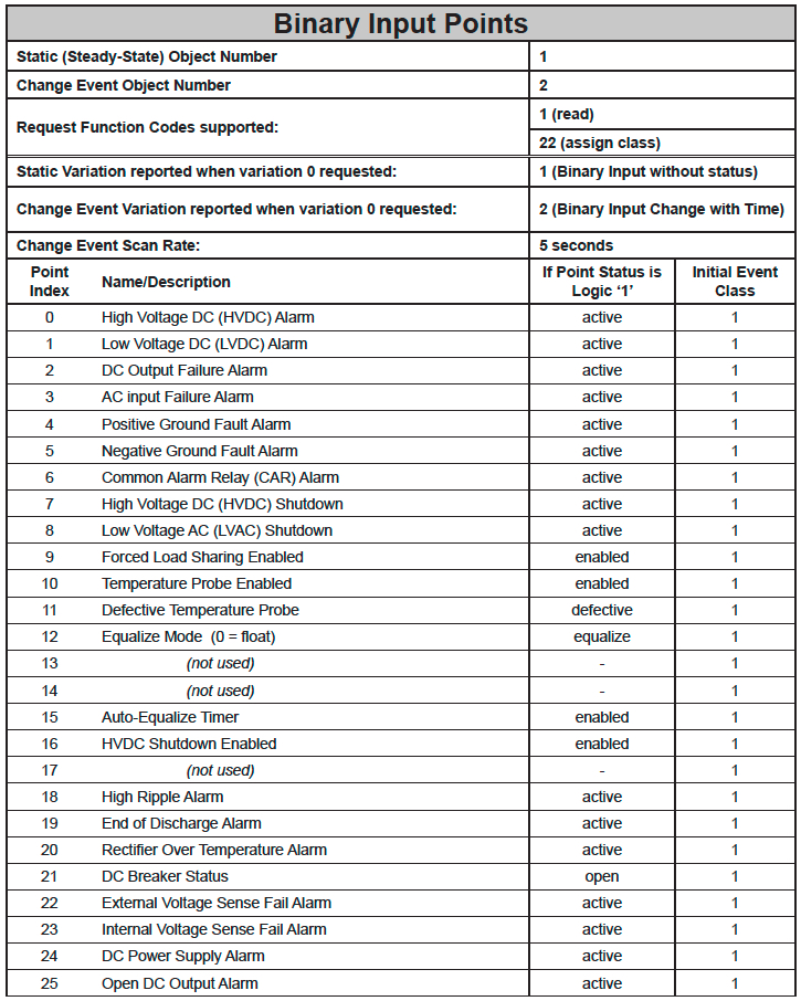
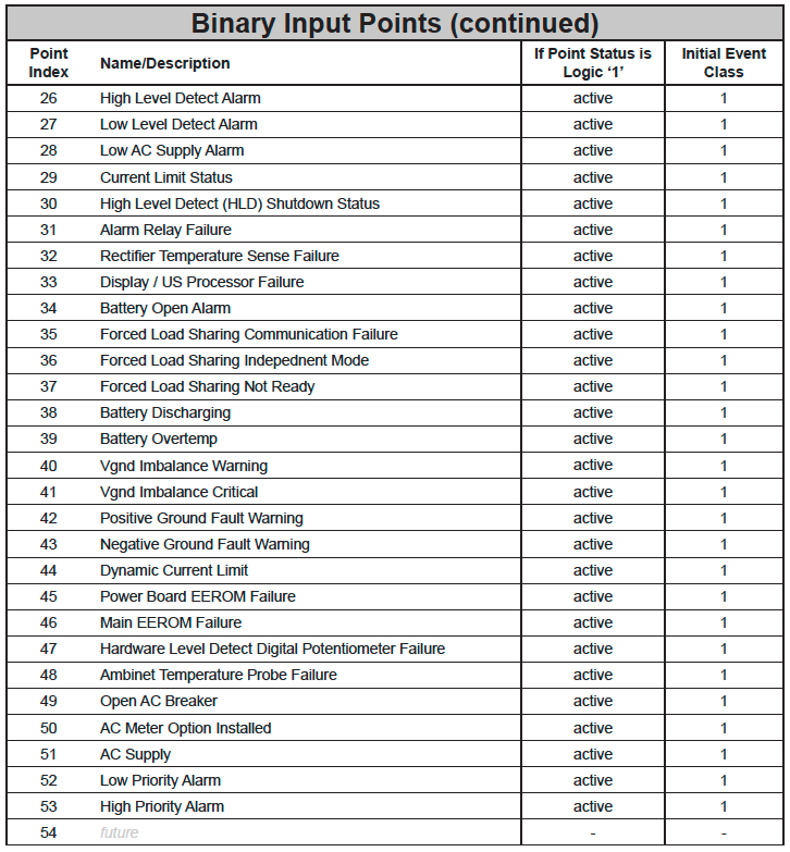
- Binary Input Points
-
![]()
![]()
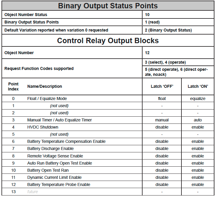
- Binary Output Points
-
![]()
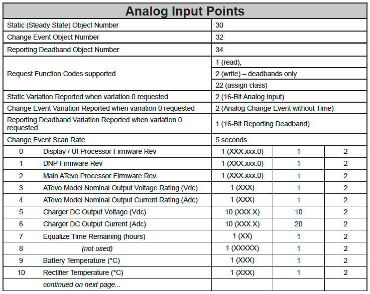
- Analog Input Status Points
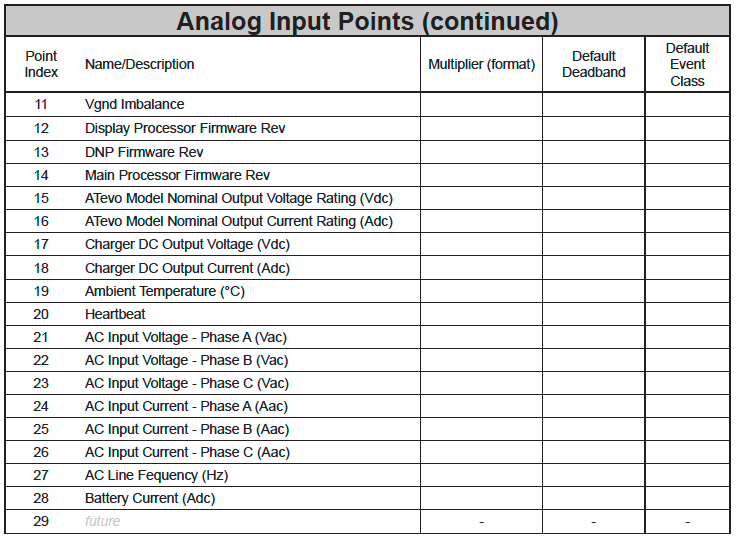
- The following table lists Analog Inputs. It is important to note that 16-bit and 32-bit variations of Analog Inputs, Analog Output Control Blocks, and Analog Output Statuses are transmitted through DNP as signed numbers. Even for analog input points that are not valid as negative values, the maximum positive representation is 32767. The “Multiplier” column indicates the value by which each data point is multiplied. Since all data points are sent in integer format, floating point numbers are multiplied by a constant (1, 10, or 100) to maintain decimal information. For example, points with two decimal places of resolution are multiplied by 100 (5.67 is sent as 567) while points with one decimal place of resolution are multiplied by 10 (8.2 is sent as 82). To convert a data point to the correct value, simply divide the point by the “Multiplier” value.
![]() The “Default Deadband” column is used to represent the absolute amount by which the point must change before an analog change event will be generated. The “Default Event Class” column is used to represent the class (1, 2, 3, or none) in which detected change events will be reported. Only the default values for these columns are shown here because the values may change in operation due to either local (user-interface) or remote (through DNP) configuration control.
The “Default Deadband” column is used to represent the absolute amount by which the point must change before an analog change event will be generated. The “Default Event Class” column is used to represent the class (1, 2, 3, or none) in which detected change events will be reported. Only the default values for these columns are shown here because the values may change in operation due to either local (user-interface) or remote (through DNP) configuration control.![]()
![]()
![]()
![]()
- Upper 8 bits of register value are the Major Version
- Lower 8 bits of register value are the Minor Version
- Example: Version 10.6.0 would be 0×0A06 (hex) = 2566 (decimal)
- Analog Output Status Points
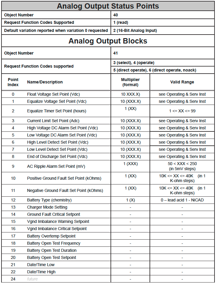
- The following table lists Analog Outputs (Object 40). The valid range for many of these points depends on the ATevo model type (dc voltage and dc current rating). Refer to the main ATevo ‘battery charger’ Operating & Service Instructions manual (JA0102-51) to determine valid ranges for these set points. It is important to note that 16-bit and 32-bit variations of Analog Inputs, Analog Output Control Blocks, and Analog Output Statuses are transmitted through DNP as signed numbers. Even for analog input points that are not valid as negative values, the maximum positive representation is 32767. The “Multiplier” column indicates the value by which each data point is multiplied. Since all data points are sent in integer format, floating point numbers are multiplied by a constant (1, 10, or 100) to maintain decimal information. For example, points with two decimal places of resolution are multiplied by 100 (5.67 is sent as 567) while points with one decimal place of resolution are multiplied by 10 (8.2 is sent as 82). To convert a data point to the correct value, simply divide the point by the “Multiplier” value.
![]() When writing a value to the Analog Output, you must multiply the desired value by the constant in the ‘Multiplier’. For example, if you want to change the ‘Float Voltage Set Point’ to 132 volts, you need to write 1320 to Analog Output ‘0’ (132 × 10 = 1320); ‘10’ is the multiplier for Analog Output Point ‘0’.
When writing a value to the Analog Output, you must multiply the desired value by the constant in the ‘Multiplier’. For example, if you want to change the ‘Float Voltage Set Point’ to 132 volts, you need to write 1320 to Analog Output ‘0’ (132 × 10 = 1320); ‘10’ is the multiplier for Analog Output Point ‘0’.![]() The ‘Valid Range’ column lists the possible values that can be successfully written to the associated Analog Output point. This is the true value, and does not include the multiplier correction. Attempting to write values outside of this range will result in a DNP3 error response.
The ‘Valid Range’ column lists the possible values that can be successfully written to the associated Analog Output point. This is the true value, and does not include the multiplier correction. Attempting to write values outside of this range will result in a DNP3 error response.![]()
![]()
![]()
- Internal Indication (IIN) Bits
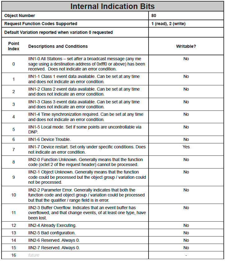
- The Internal Indication bits in the following table are defined by the DNP3 protocol.
![]()
![]()
Last modified:
8 August 2022