
ATevo Communications can support one (1) Ethernet Comm Adapter (A22). The adapter contains a standard RJ-45 connector and will support copper 10/100 Mbps Ethernet connections. It supports multiple protocols (DNP3 and Modbus) simultaneously.
Ethernet Communications Adapter Installation
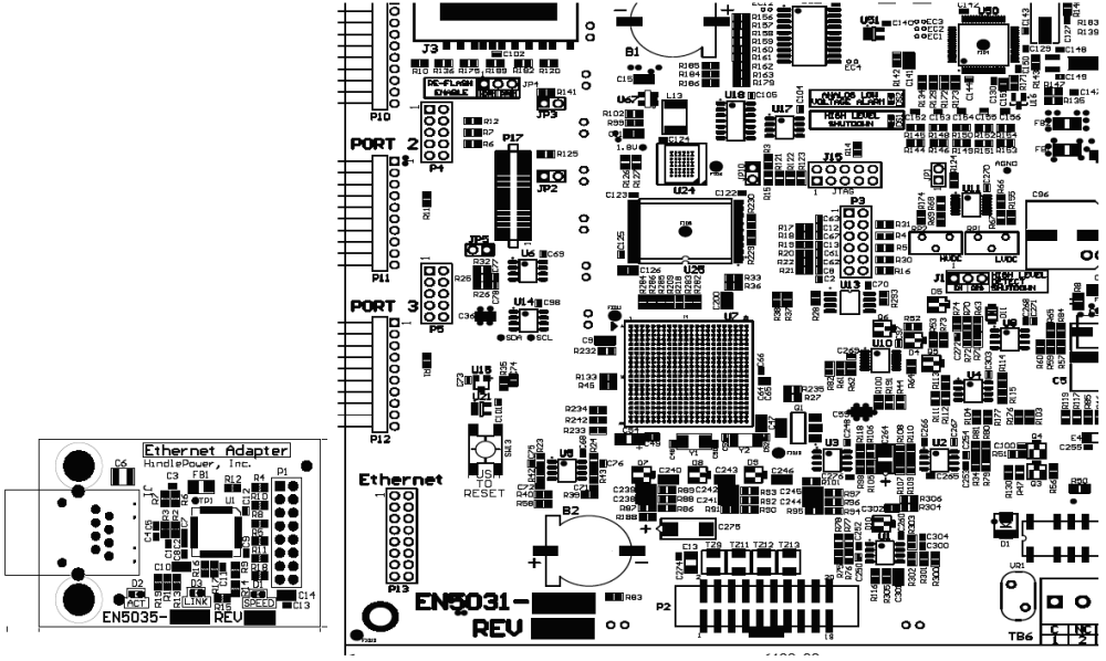
The Ethernet Communications Adapter (A22) plugs into the “Ethernet” port (P13), near the bottom-left of the Main Control Board.
To install an Ethernet Communications Adapter:
- Turn off (open) both AC Input (CB1) and DC Output (CB2) Circuit Breakers.
- Wait for charger voltage to ramp down (display will go blank and all LEDs will be off).
- Open the ATevo front panel door.
- Remove the ground connection from the lower-left corner of the Main Control PC Board (A1).
- Carefully disengage the Main Control Board from standoffs on the left side of the board.
- Locate the Ethernet Communications Adapter connection port (P13), near the bottom-left of the Main Control Board (A1).
- Carefully slide socket (P1) of the Ethernet Communications Adapter onto pins of connection port (P13) of the Main Control Board.
- Hold the Ethernet Communications Adapter (A22) at an angle to clear standoffs on the door.
- Once the Ethernet Communications Adapter socket is fully engaged on the Main Control Board header pins, line up the holes on the Ethernet Adapter (A22) with the plastic standoff pins.
- Press down on the Ethernet Communications Adapter (A22) and the Main Control Board (A1) to lock them onto the standoffs.
- Replace the ground connection on the bottom-left side of the Main Control Board.
- Close the ATevo front panel door.
- Turn on (close) the AC Input Breaker (CB1), then turn on (close) the DC Output Breaker (CB2).
- The Ethernet Communications Adapter hardware is now installed.
- Refer to Section 3.2 to assign protocol and set communications parameters (IP address, Netmask, Gateway, etc).
Ethernet Defined
Ethernet is a family of computer networking technologies used in local area networks (LANs). Several variants of Ethernet are available. Newer variants typically use copper twisted-pair or fiber optic links with hubs or switches to form the network. Ethernet permits a large number of devices to be interconnected and allows the devices to communicate via multiple protocols concurrently.
Ethernet Connections
ATevo Communications can be connected to a 10/100 Mbps Ethernet network with a standard Ethernet RJ-45 cable. Plug one end of the cable into J1 of the Ethernet Adapter (A22) and the other end into an Ethernet hub, switch or directly into the SCADA master.
Optional Fiber Ethernet Interface
Although Ethernet interfaces are standardized, many variants of Ethernet over fiber exist (75 at the time this manual was written). The variants are based on different data rates, fiber type, wavelength, and connector types.
The optional ATevo Fiber Ethernet Interface can be configured to accommodate most if not all of these variants. Due to the vast number of variants (and continuous addition of new ones), the specific offerings and capabilities needed to interface a site fiber Ethernet network must be verified with an ATevo distributor.