English
Japanese
ConveyLinx-Ai Family Complete Guide
3.1
3.1
3.0
2.1
2.0
1.7
Table of Contents
ConveyLinx-Ai Family Complete Guide
3.1
ConveyLinx-Ai Family Complete Guide — 3.1
ConveyLinx-Ai Family Complete Guide — 3.0
ConveyLinx-Ai Family Complete Guide — 2.1
ConveyLinx-Ai Family Complete Guide — 2.0
ConveyLinx-Ai Family Complete Guide — 1.7
ConveyLinx-Ai Family Controllers
About This Manual
Glossary of Terms
Getting Started
Module Hardware
Module Hardware Revisions
Identifying Module Components
ConveyLinx-Ai2 / ConveyLinx-Ai2-48
ConveyLinx-Ai3-24-FC / ConveyLinx-Ai3-48-FC
ConveyLinx-Ai3-24-RC
Mounting Dimensions
ConveyLinx-Ai2 / ConveyLinx-Ai2-48
ConveyLinx-Ai3-24-FC / ConveyLinx-Ai3-48-FC
ConveyLinx-Ai3-24-RC
ConveyLinx-Ai3-24-FCM / ConveyLinx-Ai3-48-FCM
Module Power Connections
ConveyLinx-Ai2 / ConveyLinx-Ai2-48
ConveyLinx-Ai3-24-FC & FCM
ConveyLinx-Ai3-48-FC & FCM
ConveyLinx-Ai3-24-RC
Assembly Instructions
Motor and Logic Power Distribution
ConveyLinx-Ai2
ConveyLinx-Ai3-24-FC & FCM
ConveyLinx-Ai3-24-RC
ConveyLinx-Ai2-48
ConveyLinx-Ai3-48-FC & FCM
Proper Motor Grounding Practice
Power Supply Sizing
Motor Power for 24V Models
Motor Power for 48V Models
Logic Only Power
Motor Ports
Motor Ports as Digital Outputs
Sensor Ports
Electrical Connections for Sensor Port Aux I/O
Ethernet Ports
ConveyLinx-Ai3-24-FCM / ConveyLinx-Ai3-48-FCM
LED Status Indicators
Technical Specifications
Certifications & Standards
Auto-Configuration
Device Connections to Modules
Examples that will generate errors
Motor Rotation Definition
Node Connections for a Subnet
ConveyLinx Ethernet Definition
Connecting Your PC to the Network
Auto-Configuration Procedure
Expected Results
What to do if things go wrong
Default Settings and Operation
Singulation Release Mode
Flex Zone Recognition
Jam Conditions
Arrival Jam
Sensor Jam
Automatic Module Replacement
Reset to Factory Default Settings
EasyRoll Software
Installing EasyRoll
Main Screen
Node Navigation
Node Identification
ZPA Upstream/Downstream Zone Settings
Release Mode
Singulation Release
Train Release
GAP Train Release
T-Zone Settings
ZPA Error and Information
Accumulate Control from Main Screen
Settings Checkboxes
Disable Reset Delays
Disable Sensor Jam Auto Clear
Disable Arrival Timeout
Disable Manual Operation
Last Zone Recommendation
Motor Settings
Motor Type
Brake Method
Speed
Rotation Direction
Acceleration/Deceleration
Motor Jog and Error Indicators
PGD Motor Pulse Distance Calculation
Diagnostic Window
Advanced Dialog
Look Ahead and Timing Tab
Look Ahead Slowdown Feature
Jam & Auto Clear Timers
Run After Time/Distance
Induct Forward Time/Distance
Sensor Debounce
Upgrade Tab
Connections Tab
Network Services Tab
Discover & IP Address Set
Backup & Restore
Special Services Tab
Flex Zone Tab
Sensors Tab
Extensions Tab
Pin 2 Usage Tab
Most Downstream Zone
Most Upstream Zone
Accumulate Intermediate Zone
Lane Full Interface
Most Upstream Zone Handshake Interlock
Most Downstream Zone Handshake Interlock
Inverting the Pin 2 Signals
EasyRoll+ Software
ConveyMerge
ConveyMerge Prerequisites and Requirements
Network Architecture
Sensor Placement
Merge Zone Module
Merging Lines
Merge Configurations
Merge Priority
T-Merge Settings
Configuring Dynamic Priority Release
Enabling ConveyMerge from EasyRoll
Conventional Spur Merge Example
T-Merge Example
Merge Line Full Example
IOX Interface Module
Wake up and/or Lane Full Interface
Wake up/Lane Full with Wired Terminals
Wake up/Lane Full with Discrete Signals
Wake up/Product on Zone Handshake Interlock
Downstream/Product on Zone Handshake Interlock
Pin 2 Output on Aux I/O M8
Pin 2 Output on Wired Terminals
Setting Up Dual Motor Zones
Two Ai MDRs Mechanically Coupled
ZPA Mode
PLC I/O Mode
ConveyLogix Program
Two Ai Motors in One Roller Tube (Dual Drive)
Two Motor Rollers in One Logical Zone Not Coupled
PLC Developers Guide
Network Architecture
Understanding Assemblies
Modbus Assembly Instance Structure
Ethernet I/P Assembly Instance Structure
Profinet IO Assembly Instance Structrure
Assembly Register Chart Legend
ZPA Mode Control
PLC Inputs for ZPA Mode
Local Zone Status
Arrival/Departure Counts
Module Status
Tracking and Release Counts
Forward and Reverse Tracking
Port Inputs and ConveyStop Status
PLC Outputs for ZPA Mode
Set Local Tracking
Accumulation Control
Speed Control
Release and Status
Induct Tracking Forward and Reverse
Set Outputs and Motor Clear
ConveyStop and Clear Jams
Direction and Accumulation Mode
ConveyMerge Interface
ZPA Examples
Basic Accumulate and Release with Tracking Data
Conveyor Setup for Simple Bar Code Reader
Upstream Accept Interface
Downstream Discharge Interface
Simple Divert Example
Merge onto ZPA Main Line
Reduced Size ZPA Mode Assemblies
PLC I/O Mode Control
Setting PLC I/O Mode in EasyRoll
Optional Clear Connections Choice
Configuring Action for Loss of Communication
PLC Inputs for PLC I/O Mode
ConveyStop Status
Sensor Ports
Left Motor Status
Right Motor Status
Motor Ports Digital Status
Upstream / Downstream Status & Tracking
Servo Control Status
PLC Outputs for PLC I/O Mode
ConveyStop Command & Clear Motor Error
Motor & Sensor Port Digital Output
Left Motor Control
Right Motor Control
Set Status & Tracking
Set Sensor Port Input Mask
Servo Control
Servo Control Example
Reduced Size PLC I/O Mode Assemblies
ConveyLogix Interface
ConveyLogix Assembly Inputs to PLC
ConveyLogix Assembly Outputs from PLC
Assemblies with Reset Protection
ZPA Mode Assembly Inputs with Reset Protection
ZPA Mode Assembly Outputs with Reset Protection
Reduced Size ZPA Mode Assemblies with Reset Protection
PLC I/O Mode Assembly Inputs with Reset Protection
PLC I/O Mode Assembly Outputs with Reset Protection
Reduced Size PLC I/O Mode Assemblies with Reset Protection
How to use Assemblies with Reset Protection
Motor Port as Digital I/O
Connecting to Rockwell PLCs with Ethernet I/P
Selecting Your Connection Method based upon Assembly
Using Generic Ethernet Module Method
Procedure for Connecting using Generic Ethernet Module
Parameters for Each Assembly
Procedure for using EDS Method
Using Add On Instructions (AOI) with RSLogix 5000
AOI Tag Descriptions
ZPA Mode Inputs
ZPA Mode Outputs
PLC I/O Mode Inputs
PLC I/O Mode Outputs
Using Logix 5000 MSG Instruction
Read MSG Instruction
Write MSG Instruction
Reading an Input Assembly with MSG Instruction
EDS Module Data Type Cross Reference
Connecting to Siemens PLC with Profinet IO
Preparing Your Programming Environment
Modes of Operation
Understanding the Two Configuration Methods
Separate ConveyLinx Auto-Configuration
Profinet Name
Examples of Adding Modules
Full ZPA
Full PLC Controlled
Reduced ZPA
Reduced PLC
Merger Mode
PLC Controlled with ConveyLogix Interface
Integrated PLC Topology Configuration
Profinet Name
Adding Modules
Topology Example
Connecting 1st Subnet of Modules
Connecting 2nd Subnet of Modules
Module Configuration
ZPA/Reduced ZPA Modes
Upstream/Downstream Zones
Upstream/Downstream Zone Timing
Sensor Port Pin 2 Usage
Connection to Merger Module
PLC/Reduced PLC Mode
Merger Mode
ConveyLogix Mode
Accessing Data from ConveyLinx Modules
Raw Unmapped Data Direct from Module
Module Data Elements Mapped to Tags
Module Data Instances Mapped to User Defined Types (UDTs)
Installing UDTs into Programming Environment
Selecting the correct UDT for the Module’s Assigned DAP
UDT Assignment Example
Add feeder Module
Add workstation Module
Add remaining Modules
User Data Types (UDTs)
UDTs for Ai2 Family
Full ZPA Mode Inputs
Full ZPA Mode Outputs
Reduced ZPA Mode Inputs
Reduced ZPA Mode Outputs
Full PLC Mode Inputs
Full PLC Mode Outputs
Reduced PLC Mode Inputs
Reduced PLC Mode Outputs
Troubleshooting
Download as PDF
ConveyLinx-Ai3-24-RC
ConveyLinx-Ai3-24-FC / ConveyLinx-Ai3-48-FC
ConveyLinx-Ai3-24-FCM / ConveyLinx-Ai3-48-FCM
Module Hardware
/
Mounting Dimensions
/
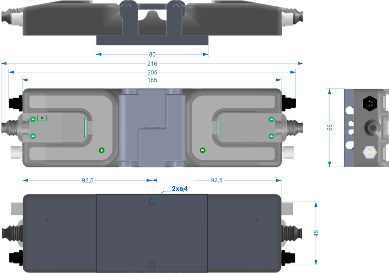
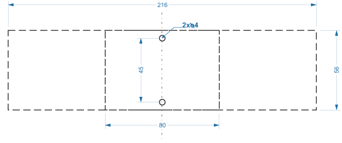
ConveyLinx-Ai3-24-RC
Module Dimensions
Mounting Hole Dimensions
ConveyLinx-Ai3-24-FC / ConveyLinx-Ai3-48-FC
ConveyLinx-Ai3-24-FCM / ConveyLinx-Ai3-48-FCM