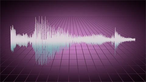
Generate waveform patterns based on an audio layer. The waveform scrolls along a line, whose position is determined using end points, and its color and appearance is fully customizable.
Audio Input
- Audio Layer: Choose any layer containing audio, to use its audio as the source for generating the waveform. The effect examines the audio levels and frequencies present in the selected layer, and generates a waveform that displays that data.
- Channel: Select the audio channel from the source layer that will be used to generate the waveform.
- Left: Uses the left audio channel from the layer.
- Right: Uses the right audio channel from the layer.
- Average: Combines the values from the left and right channels then divides by two, and uses that average value.
- Duration: Sets the duration of the source file which will be visible at any given time. This will also affect the speed at which the waveform scrolls, with lower values creating faster movement. At very low values, you will see more frantic movement, rather than a recognizable waveform. In this example, the Duration is set to 10 ms.
![]()
- Offset: Allows you to shift the visuals through time in relation to the source audio. Negative values will cause the visuals to appear after their corresponding audio. Positive values will cause the visuals to appear before their corresponding audio.
- Sampling: Controls the number of samples displayed in the visual spectrum.
- Adaptive: Evaluates the audio track, and determines how many samples to use based on the contents of the audio.
- Custom: Allows you to specify the exact number of samples used, using the Number of Samples slider that appears when this option is selected.
Audio Start
- Position: Defines the origin point of the waveform effect toward which the waveform will scroll.
- Use Layer: Select another layer from the timeline using this menu, to use the selected layer’s position to control the start position of the waveform. When a layer is selected, the Position property above functions as an offset from the parent layer’s position.
Audio End
- Position: Defines the origin point of the spectrum effect from which the waveform will scroll.
- Use Layer: Select another layer from the timeline using this menu, to use the selected layer’s position to control the end position of the waveform. When a layer is selected, the Position property above functions as an offset from the parent layer’s position.
Colors
- Preset: Choose from one of many built-in presets. Presets can be used as-is, or serve as a starting point for further adjustment of settings.
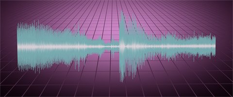
- Interpolation: Controls how the colors are mapped onto the effect. The following three examples all use the same gradient from white to teal, so you can see the difference in each interpolation method.
- Distance: Maps the color gradient vertically onto the total height of each sample of the spectrum. As the height of each sample changes, the length of the gradient will shift to match the height.
![]()
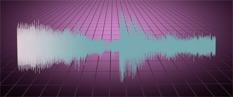
- Time: Maps the color gradient horizontally across the entire spectrum effect, starting at the start point, and ending at the end point.
![]()
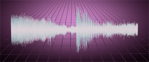
- Amplitude: Maps the color gradient vertically onto the total height of the spectrum effect, so the position of each color in the gradient is fixed, and the samples move through them as their height changes.
![]()
- Distance: Maps the color gradient vertically onto the total height of each sample of the spectrum. As the height of each sample changes, the length of the gradient will shift to match the height.
- Number of Colors: Sets the number of different colors used to create the gradient. Separate numbered color controls will be displayed below for as many colors as you select here.
- Color Controls (Numbered)
- Radius: Controls the position of the color’s center along the total length of the gradient. A value of 0.00 places it all the way at the start position, and a value of 1.00 placed it all the way at the end position.
- Color: Choose a color. You can use the eyedropper to choose a color from the layer, or click the swatch to open a color picker and choose any color you prefer. You can also manually enter the color values for the red, green, and blue channels.
- Alpha: Sets the transparency of the color. 0.00 is completely transparent, and 1.00 is completely opaque.
- Height: Defines the overall height of the spectrum, in pixels.
- Thickness: Defines the thickness of each visual sample. Lower values give a finer degree of detail, while higher values will use fewer points to generate the visual spectrum.
- Render Mode: Choose how the spectrum is drawn. Each of the following examples uses the exact same audio input, so you can see how each option differs from the others.
- Points: Only the point marking the top of each sample is drawn.
![]()
- Lines: A solid line is drawn, connecting each sample to the samples on either side of it.
![]()
- Fill: A baseline is combined with a solid line connecting all sample points, and filled to create a solid shape.
![]()
- Bar Graph: Each sample is drawn as an individual vertical line.
![]()
- Points: Only the point marking the top of each sample is drawn.
- Amplitude Transform: Controls how the color gradient is mapped onto the effect.
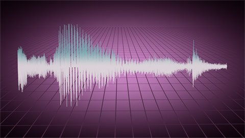
- None: The default option. The color radius is mapped from 0.00 at the center line, to 1.00 at the lowest point of the waveform.
![]()
- Flip: Flips the effect upside down, so radius values of 1.00 are mapped to the highest point in the waveform.
![]()
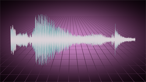
- Mirror: Combines the original and flipped versions, so radius values of 1.00 are mapped to both the top and bottom of the waveform, with the center line remaining at 0.00, creating a symmetrical effect.
![]()
- None: The default option. The color radius is mapped from 0.00 at the center line, to 1.00 at the lowest point of the waveform.
- Blend: Controls how the effect is combined with the contents of the layer it is applied to.