Raptor Drive and Controller Technical Guide
1
1.1
1
Table of Contents
Raptor Drive and Controller Technical Guide
1
Raptor Drive and Controller Technical Guide — 1.1
Raptor Drive and Controller Technical Guide — 1
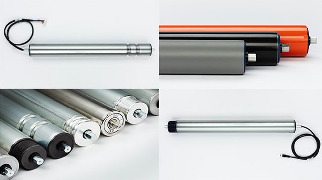
Raptor-Ai-ST Motor Roller
Available Models
General Specifications
Mechanical Materials & Options
Load Capacity
Minimum Roller Length
Approximate Finished Weight
Available Materials & Interlocking & Lagging
Interlocking Options & Drawings
Lagging / Coating Options
Performance Data
Ordering Information
Mounting Options
Installation Instructions
RaptorLinx-Ai-ST Controller
About This Manual
Controller Hardware
Identifying Module Components
Mounting Dimensions
Power Connector
Motor Port
Discrete Input Terminal
Discrete Output Terminal
Sensor Ports
Electrical Connections for Sensor Port Aux I/O
Ethernet Ports
LED Status Indicators
Technical Specifications
Certifications & Standards
Power Supply & Wiring
Power Supply Sizing
Motor and Logic Power
Digital Inputs Wiring
Digital Outputs Wiring
Proper Motor Grounding Practice
Stand Alone Operation
Node Connections for a Subnet
ConveyLinx Ethernet Definition
Connecting Your PC to the Network
Auto-Configuration Procedure
Expected Results
What to do if things go wrong
Default Settings and Operation
Reset to Factory Default Settings
EasyRoll Software
Main Screen
Node Navigation
Node Identification
Motor Settings
Motor Type
Brake Method
Speed
Rotation Direction
Acceleration/Deceleration
Motor Jog and Error Indicators
Diagnostic Window
Advanced Dialog
Upgrade Tab
Connections Tab
Network Services Tab
Discover & IP Address Set
Backup & Restore
Special Services Tab
Pin 2 Usage Tab
IOX Interface Module
PLC Developers Guide
Network Architecture
Understanding Assemblies
Modbus Assembly Instance Structure
Ethernet I/P Assembly Instance Structure
Profinet IO Assembly Instance Structrure
Assembly Register Chart Legend
PLC I/O Mode Control
Setting PLC I/O Mode in EasyRoll
Optional Clear Connections Choice
Configuring Action for Loss of Communication
PLC Inputs for PLC I/O Mode
Sensor Ports
Left Motor Status
Right Motor Status
Upstream / Downstream Status & Tracking
Servo Control Status
PLC Outputs for PLC I/O Mode
Motor & Sensor Port Digital Output
Left Motor Control
Right Motor Control
Set Status & Tracking
Set Sensor Port Input Mask
Servo Control
Servo Control Example
Reduced Size PLC I/O Mode Assemblies
ConveyLogix Interface
ConveyLogix Assembly Inputs to PLC
ConveyLogix Assembly Outputs from PLC
Assemblies with Reset Protection
PLC I/O Mode Assembly Inputs with Reset Protection
PLC I/O Mode Assembly Outputs with Reset Protection
Reduced Size PLC I/O Mode Assemblies with Reset Protection
How to use Assemblies with Reset Protection
Connecting to Rockwell PLCs with Ethernet I/P
Selecting Your Connection Method based upon Assembly
Using Generic Ethernet Module Method
Procedure for Connecting using Generic Ethernet Module
Parameters for Each Assembly
Procedure for using EDS Method
Using Add On Instructions (AOI) with RSLogix 5000
Using Logix 5000 MSG Instruction
Read MSG Instruction
Write MSG Instruction
Reading an Input Assembly with MSG Instruction
EDS Module Data Type Cross Reference
PLC I/O Mode Inputs
PLC I/O Mode Outputs
Connecting to Siemens PLC with Profinet IO
Preparing Your Programming Environment
Modes of Operation
Understanding the Two Configuration Methods
Separate ConveyLinx Auto-Configuration
Profinet Name
Examples of Adding Modules
Full PLC Controlled
Reduced PLC
PLC Controlled with ConveyLogix Interface
Integrated PLC Topology Configuration
Profinet Name
Adding Modules
Topology Example
Connecting 1st Subnet of Modules
Connecting 2nd Subnet of Modules
Module Configuration
PLC/Reduced PLC Mode
ConveyLogix Mode
Accessing Data from ConveyLinx Modules
Raw Unmapped Data Direct from Module
Module Data Elements Mapped to Tags
Module Data Instances Mapped to User Defined Types (UDTs)
Installing UDTs into Programming Environment
Selecting the correct UDT for the Module’s Assigned DAP
UDT Assignment Example
Add feeder Module
Add workstation Module
Add remaining Modules
User Data Types (UDTs)
UDTs for Ai2 Family
Full PLC Mode Inputs
Full PLC Mode Outputs
Reduced PLC Mode Inputs
Reduced PLC Mode Outputs
Troubleshooting
Raptor-Ai-ST Motor Roller
Available Models
Raptor-Ai-ST Motor Roller
Available Models
General Specifications
Mechanical / Materials / Options
Performance Data
Drawings
Ordering Information
Mounting Options
Installation Instructions
Available Models