
Depending on the installation, a specific configuration of bus termination resistors has to be applied. Bus terminating resistors are configured by using the microswitch 2 at the device rear panel.
Installation with a single lift car
Installation schematic

Configuration of bus termination resistors
| Microswitch 2 position | |
|---|---|
| Switch A | ON |
| Switch B | ON |
Installation with two lift cars
Installation schematic
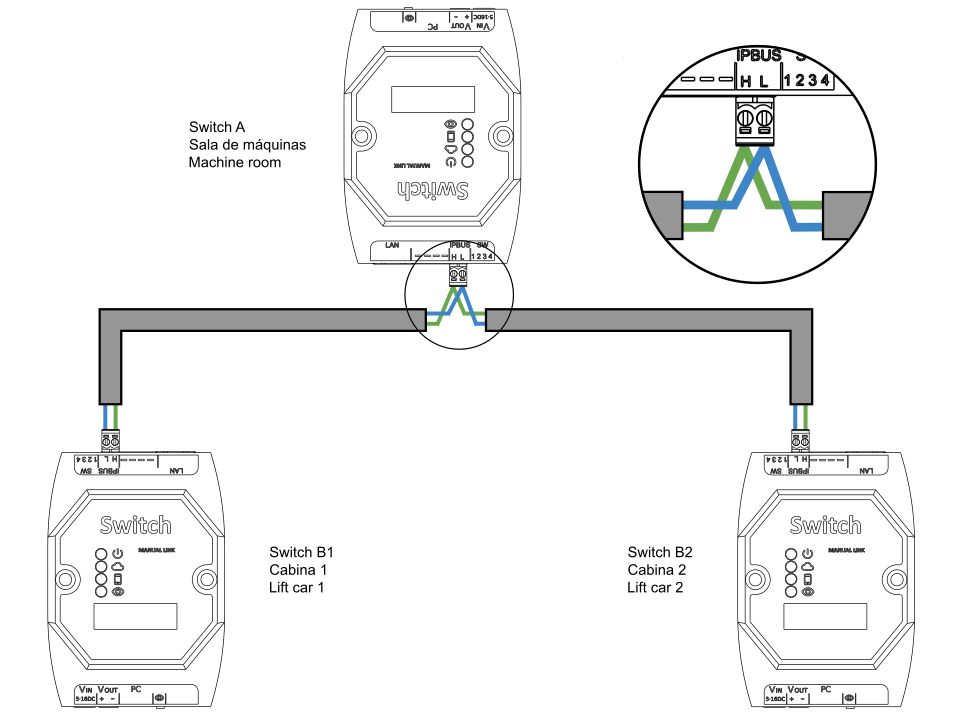
Configuration of bus termination resistors
| Microswitch 2 position | |
|---|---|
| Switch A | OFF |
| Switch B1 | ON |
| Switch B2 | ON |
Installation with three or more lift cars
Installation schematic
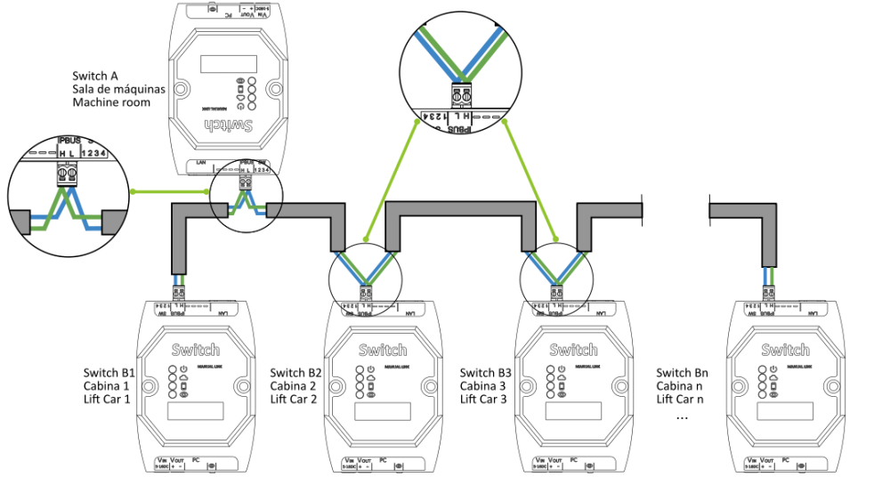
Configuration of bus termination resistors
| Microswitch 2 position | |
|---|---|
| Switch A | OFF |
| Switch B1 | ON |
| Switch B2 | OFF |
| Switch Bn | ON |
Where Bn corresponds to the Nayar Switch placed at the last lift car of the installation (it is not recommended to connect more than 8 lift cars). Therefore, the Nayar Switch whose microswitch 2 must be at ON position are those corresponding to the first and last lift car. Hereinafter, two examples of how microswitch 2 should be configured at an installation with three and four cabins are shown:
Three lift cars
| Microswitch 2 position | |
|---|---|
| Switch A | OFF |
| Switch B1 | ON |
| Switch B2 | OFF |
| Switch B3 | ON |
Four lift cars
| Microswitch 2 position | |
|---|---|
| Switch A | OFF |
| Switch B1 | ON |
| Switch B2 | OFF |
| Switch B3 | OFF |
| Switch B4 | ON |

When installation and start-up is completed correctly, all lift car Nayar Switch power and Internet connectivity LEDs should be lit up.
